Modelling:Skeleton
Infra layer of the avatar: skeleton/cartilage structure. Inspired by Reclining Woman of Henry Moore and by the Pale man of the Guillermo del Toro's Pan's Labyrinth.
This was true at the beginning of the work. In the meanwhile, a lot of other references influenced the modelling. A analysis of the blender's interface complete the research.
Contents
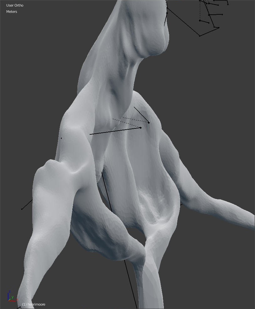
Sculpting for pleasure
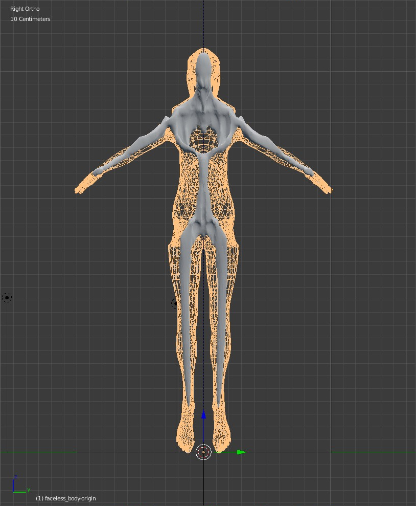
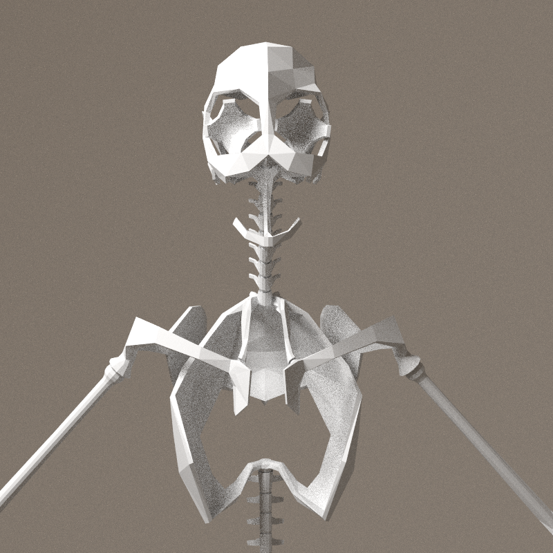
chest, head and arms
Sculpting a skeleton-like model.
Workspace, with ref images loaded on the right.

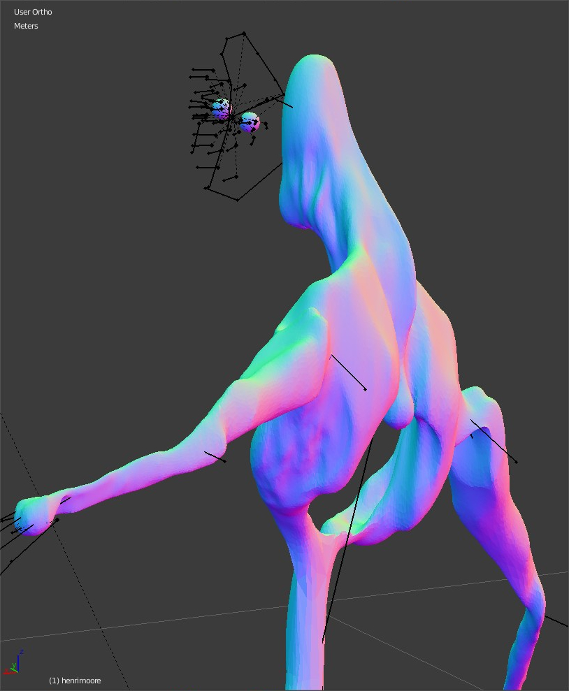
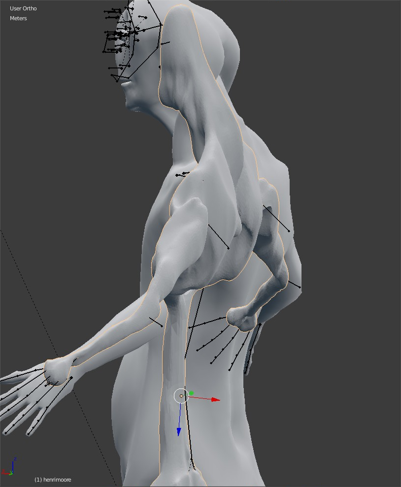
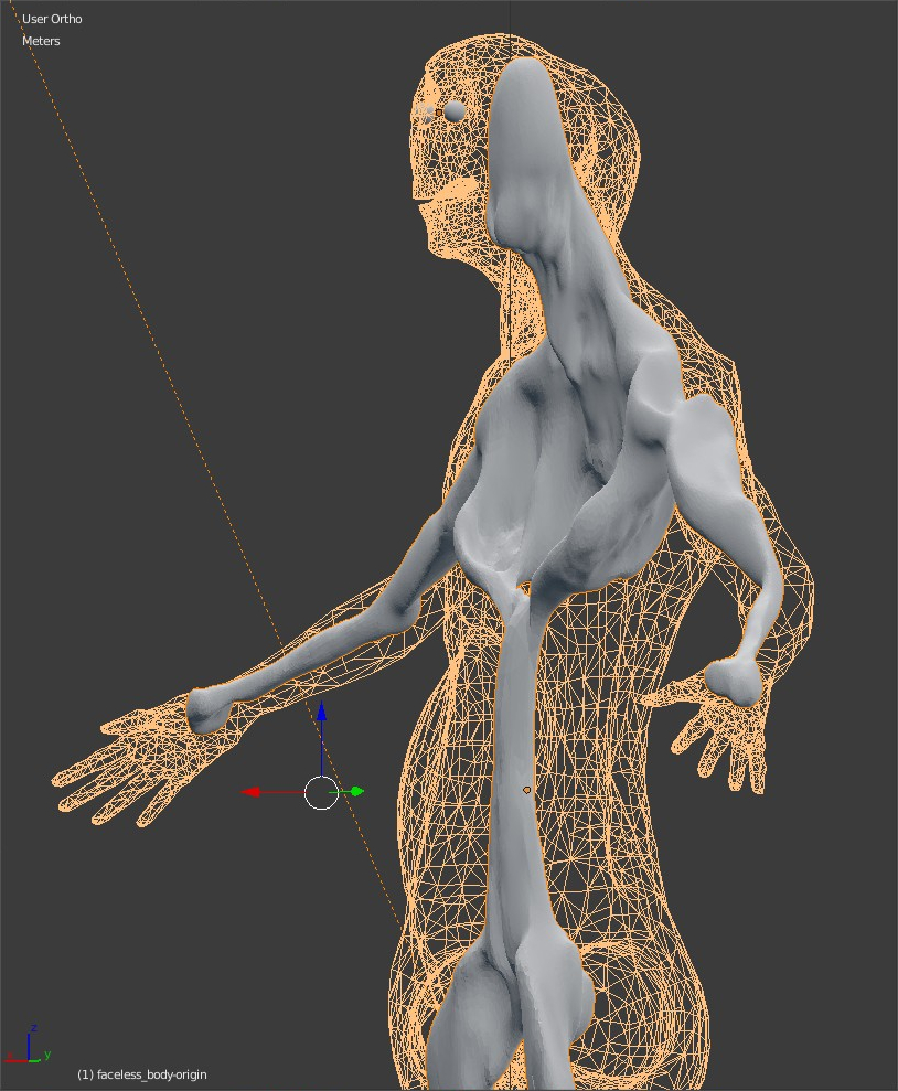
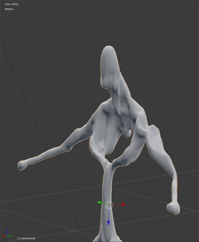
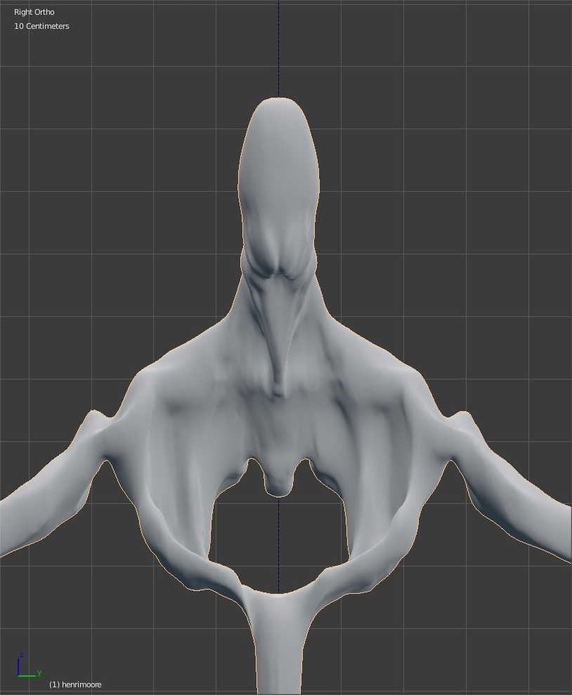
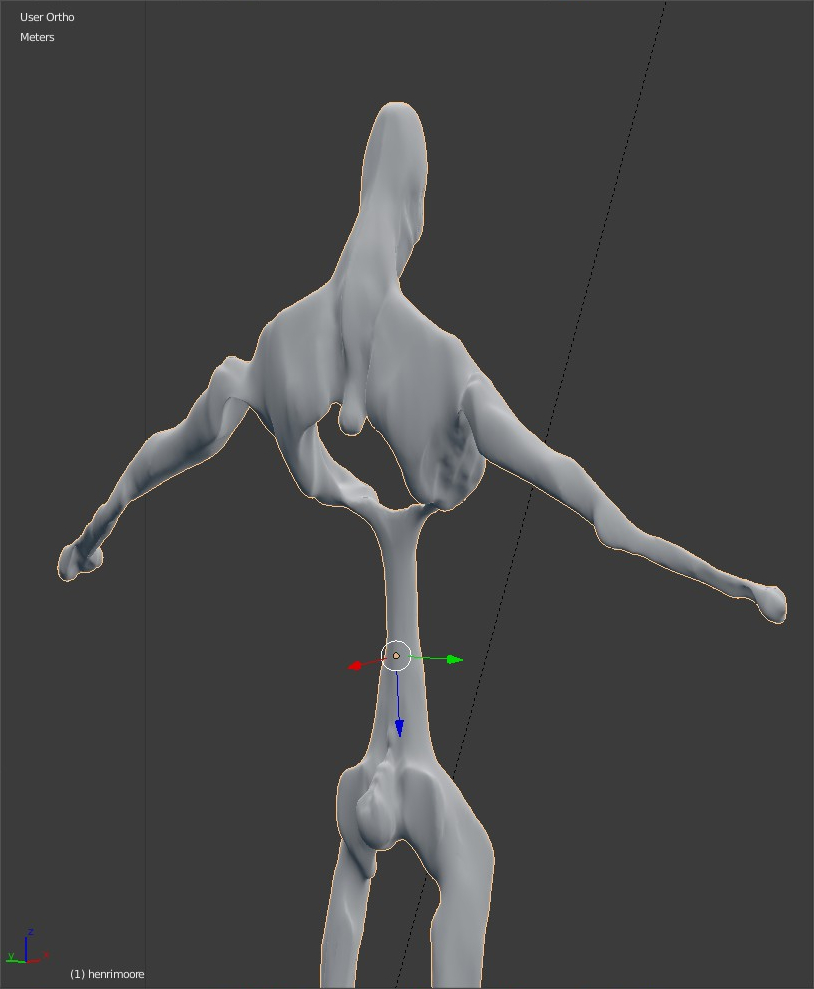
Other views


notes
- Chest is still a bit wide, belly-spine, pelvis and legs have to be fine-tuned.
- The articulation points have to be marked clearly. If the model behaves like a bone structure, the softs areas have to be tiny and concave (marked by a bevel, convex or concave)
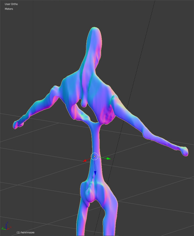
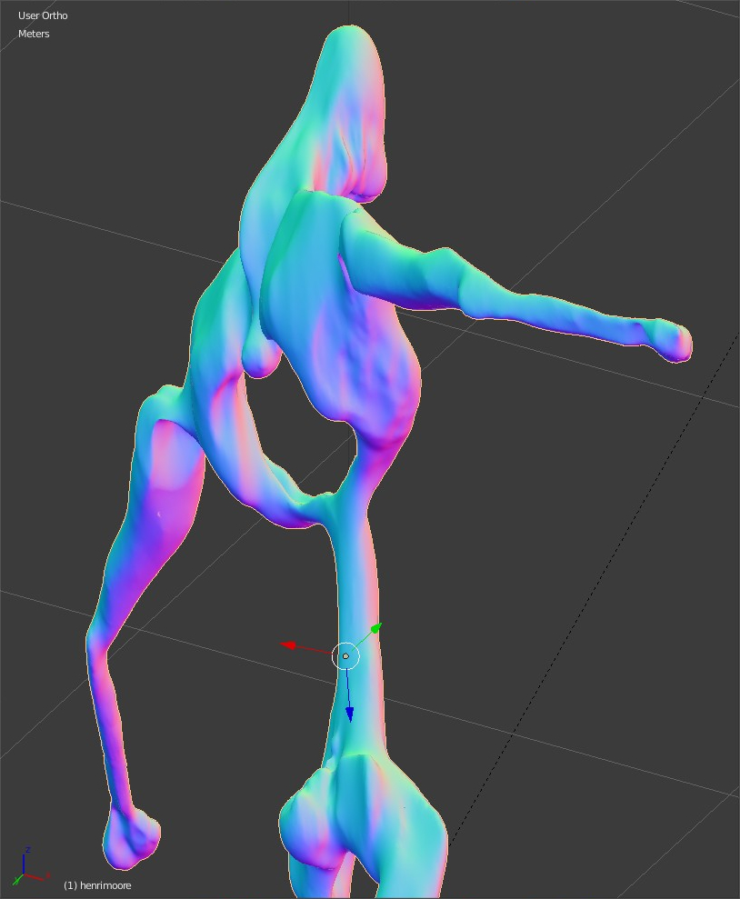
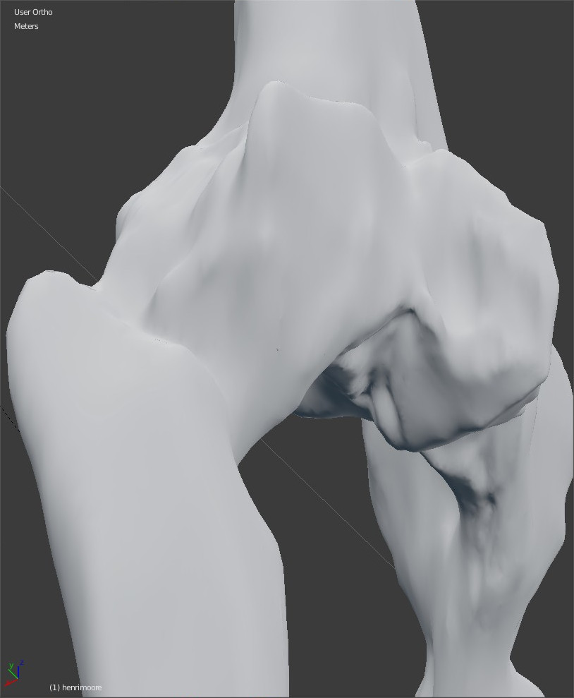
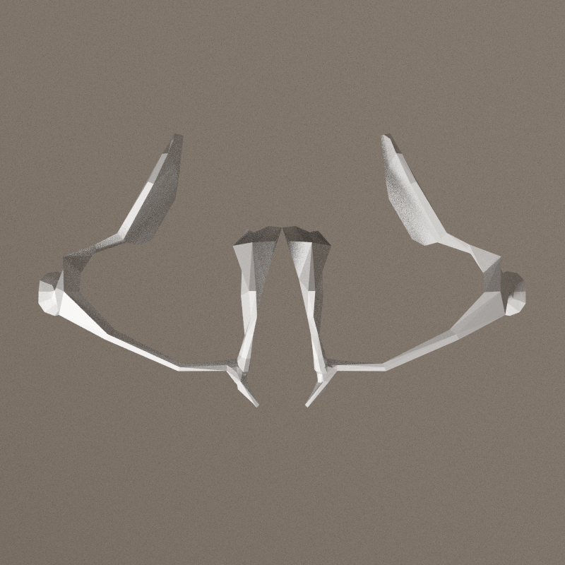
pelvis
Working on pelvis. Flaps at the back are not big enough. They should receive muscles of the legs and therefore be wider.

Skeleton consistancy
Complete handbreak: i'm masturbating on the details of the model without taking care of mechanics, without thinking to the specificity of a 3d avatar. See Theory:Avatar for the underlying thoughts.
So, back to an empty scene, just keeping the armature of a bipede, wich is the starting point of the whole modeling.
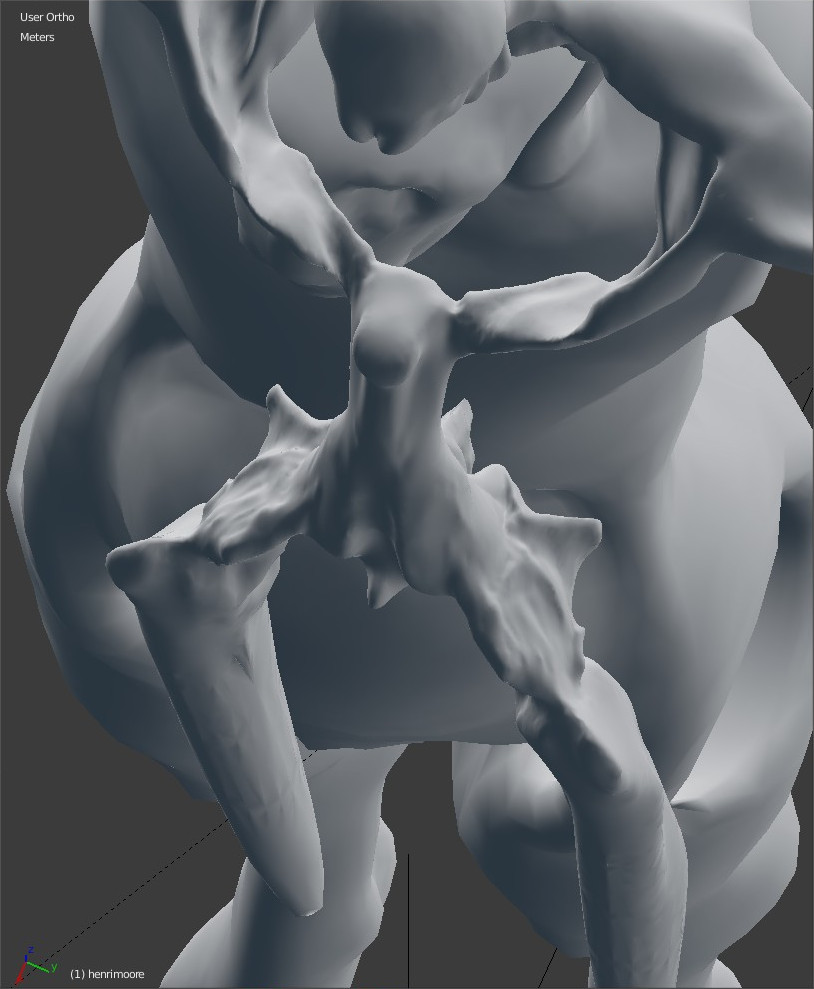
Mechanics

Each bone is conceived separately, and is an interpretation of the armature. The work of Moore is more present in the sources, and the work of Jacques Fabien Gautier d'Agoty is mounted. The way JFGdA is depicting anatomy is not scientifically correct but beautiful: the model is alive, its not a dead corpse.
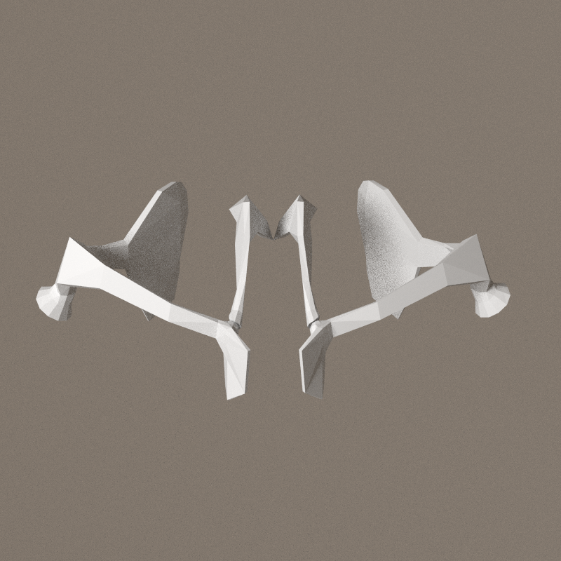
- better hips/pelvis consistancy
- pelvis will be stretch towards coxys and pubis not working, abandonned
- clavicle-neck link
- simplified hips
- no more mudguards
- with butt flaps
- begining arms and leg articulation.


- elbow articulation
- knee articulation
Just realised the articulations are absoloutly NOT functional mechanically!
Back to basics, let's study anatomy.
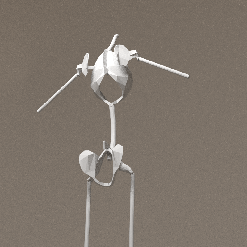
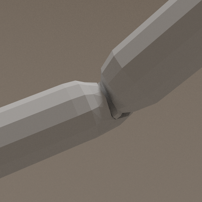
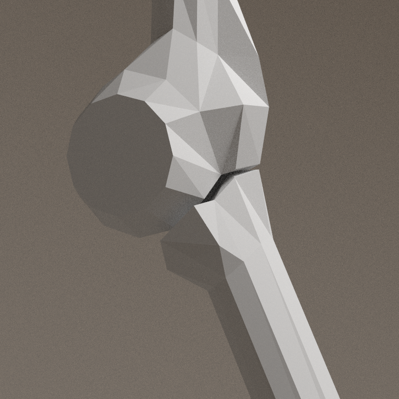
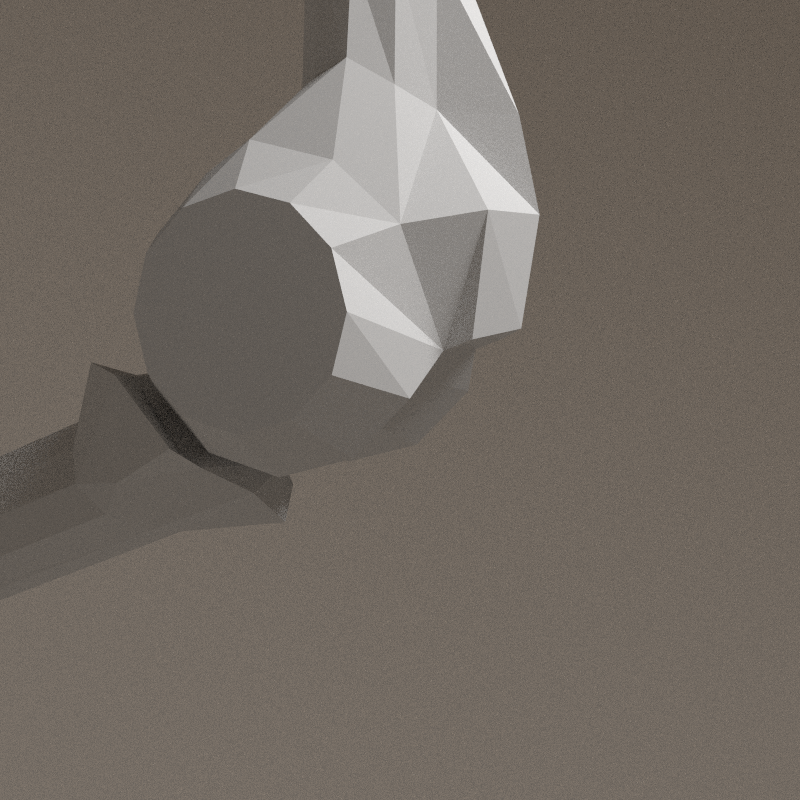
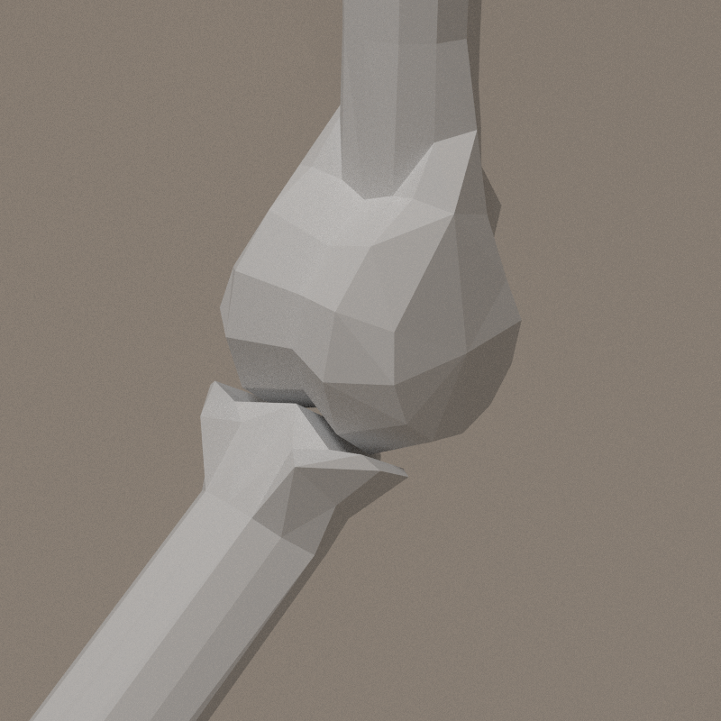
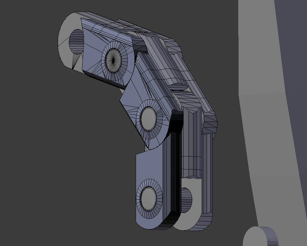
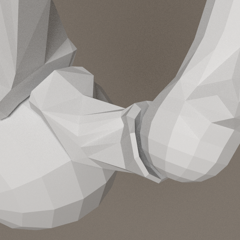
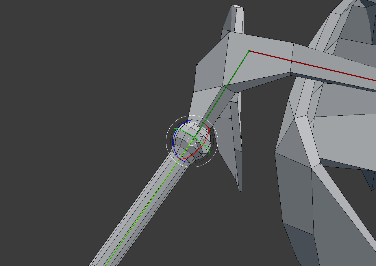
Elbow study
Taking the video into account, new meshes for arm and forearm.
- outward angle: ~19°
- inward angle: ~180°
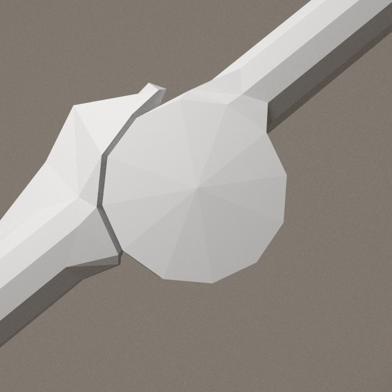
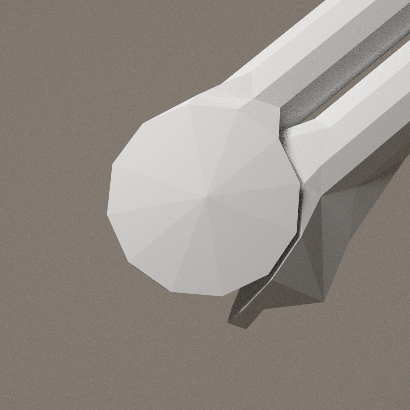
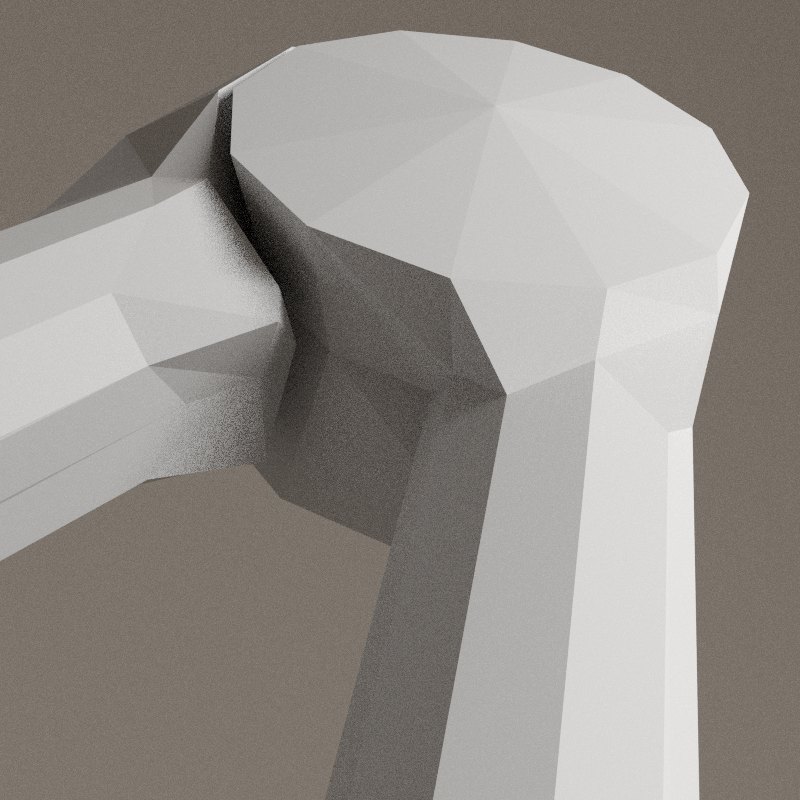

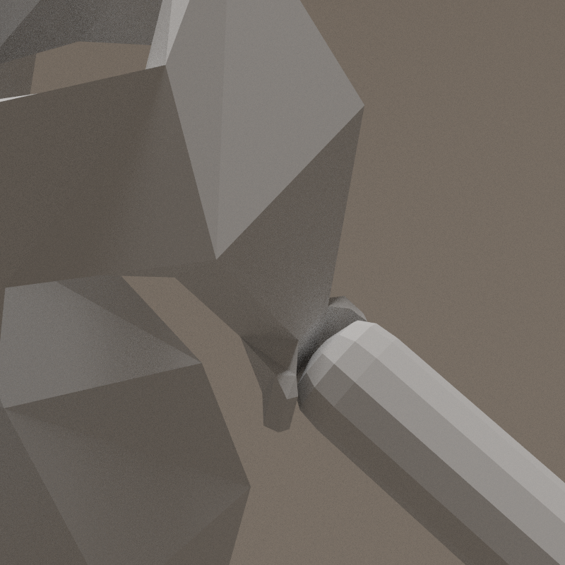
The end of the arm is finished by a cylinder perpendicular to the bone (elbow pivot). Elbow pivot have 2 times the diameter of the arm ; its center is aligned on the periphery of the arm. The pivot have a central valley that "guide" the forearm => 1 axis rotation. The forearm is just sculpted to follow the shape of the shape of the pivot.
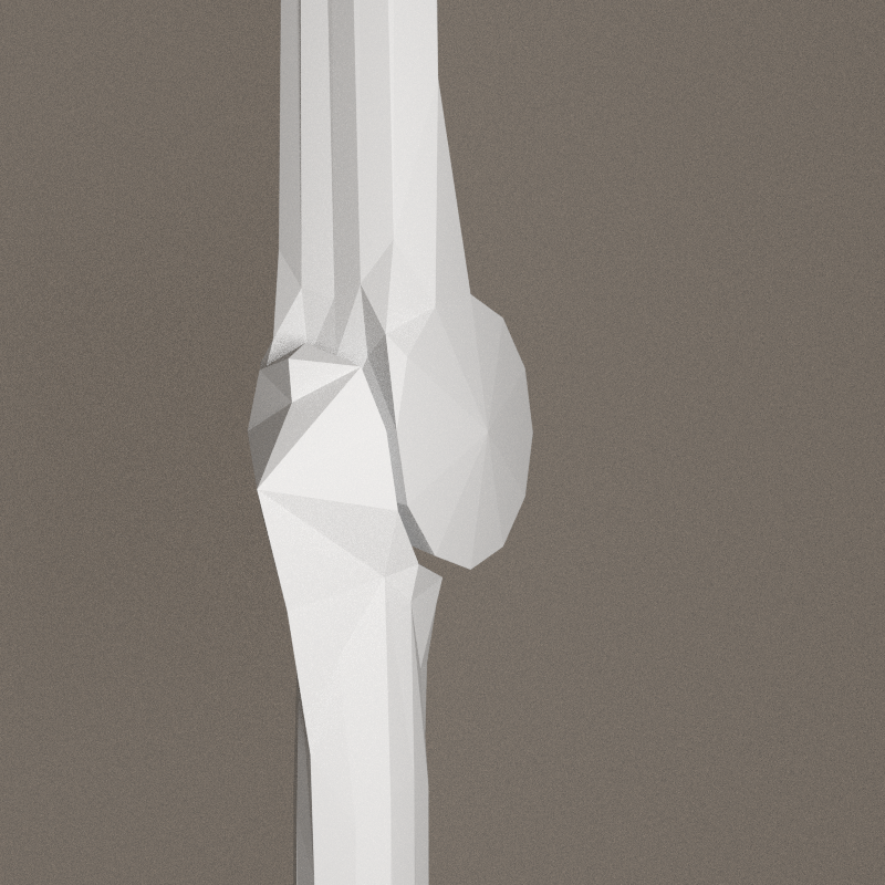
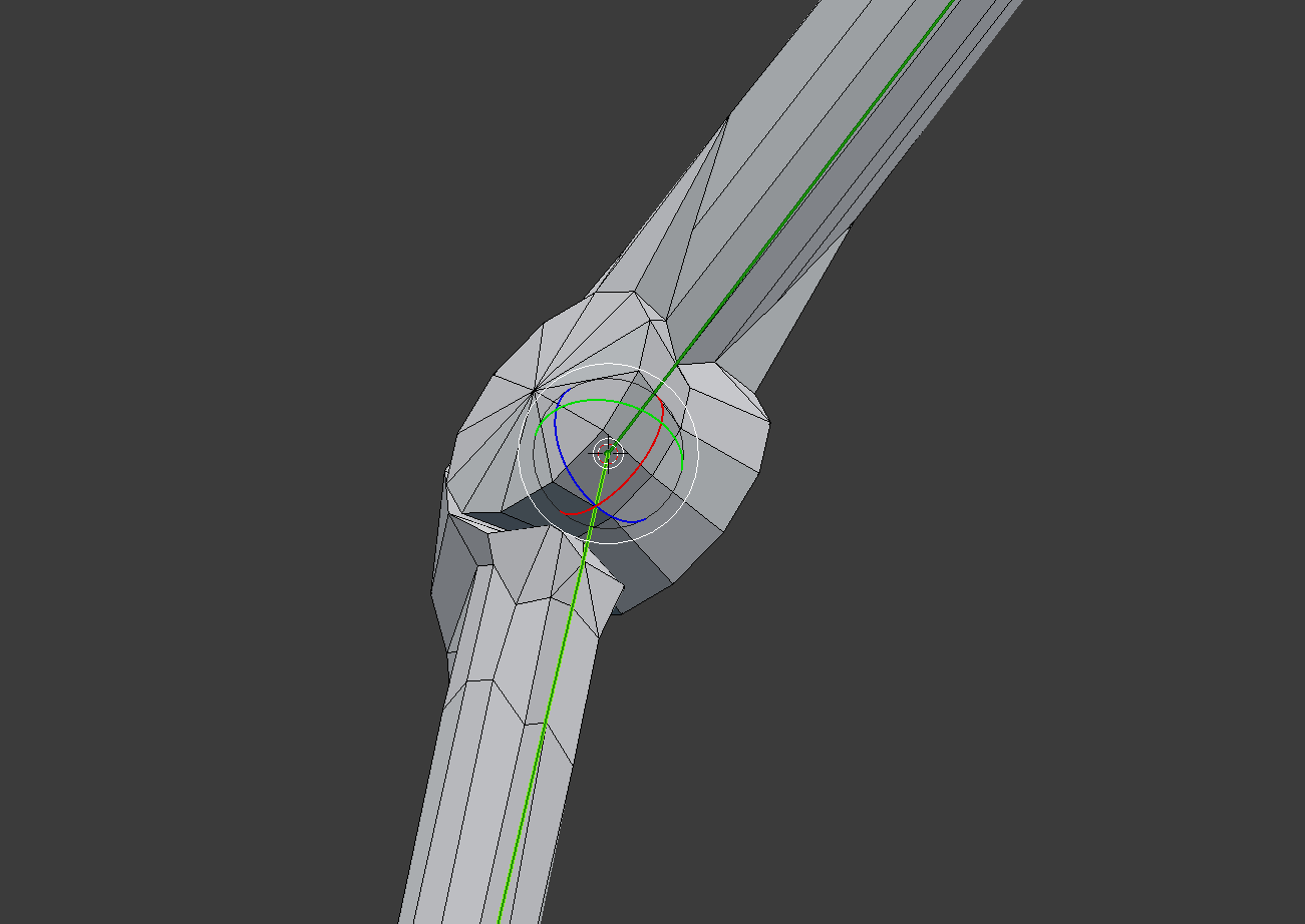
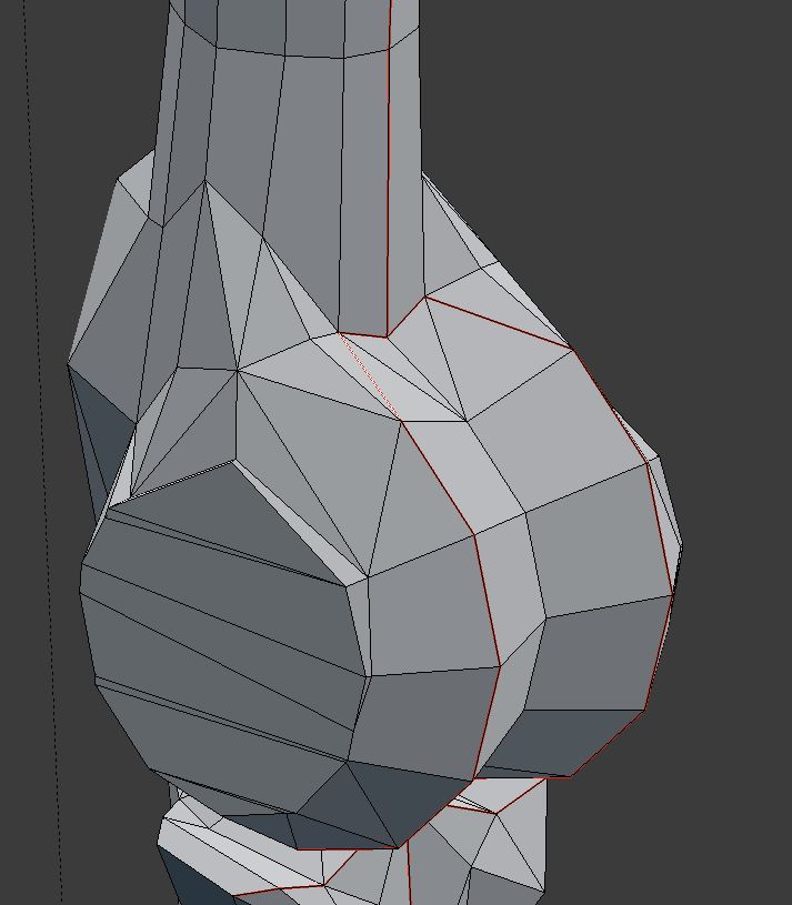
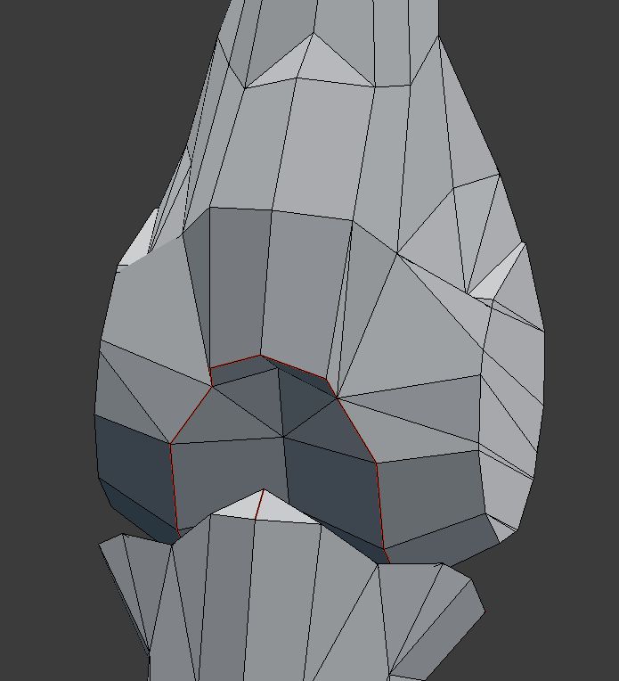
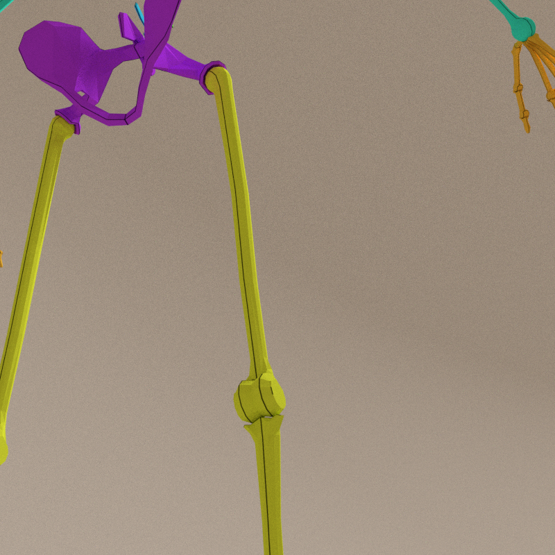
Knee study
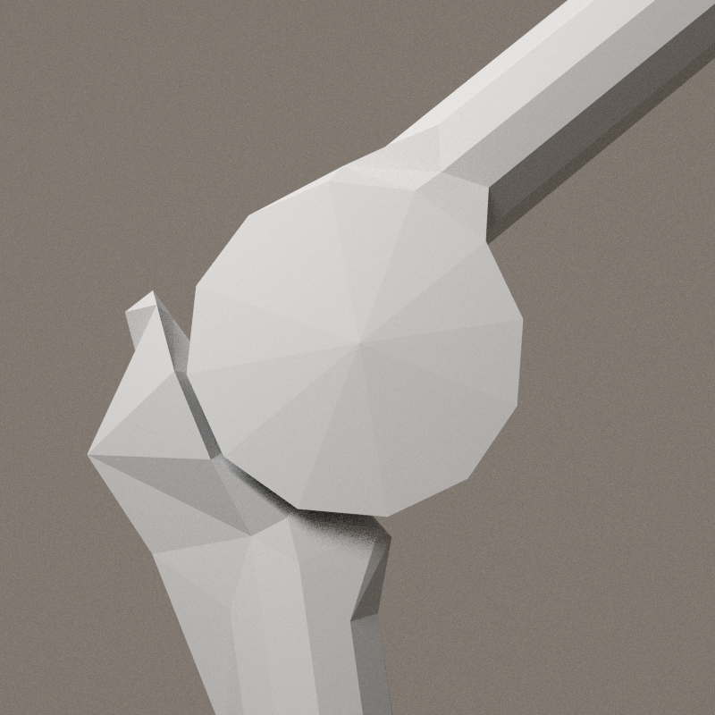
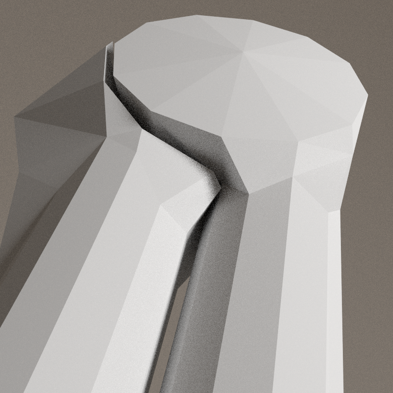
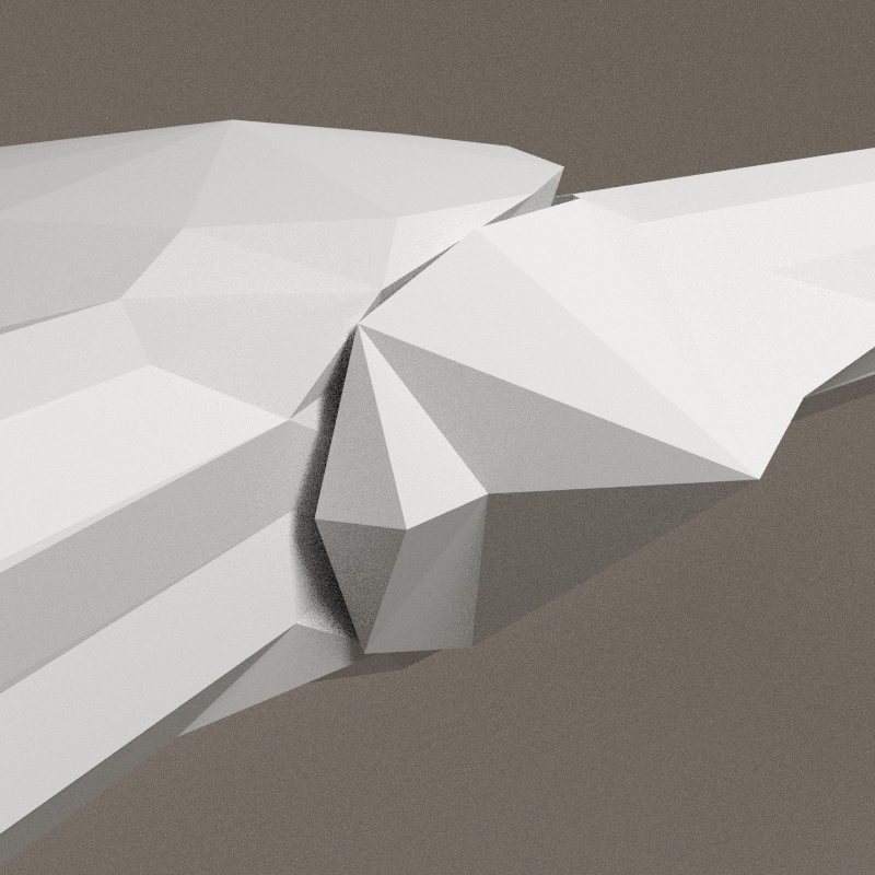
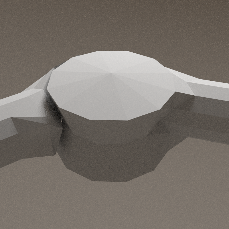
The end of the femur has a pulley shape, and the head of the tibia is a double hollowed shape. The front joint stop is stronger than the elbow.
- outward angle: ~23°
- inward angle: ~177°


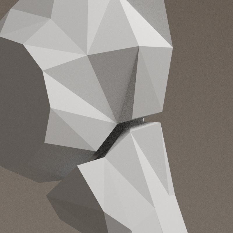
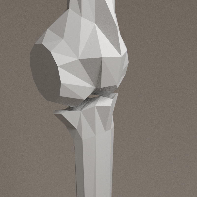

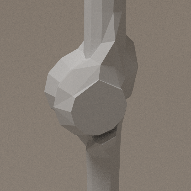
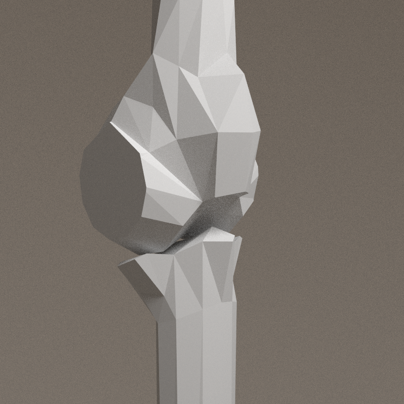
Junction with hip has to be fine-tuned.
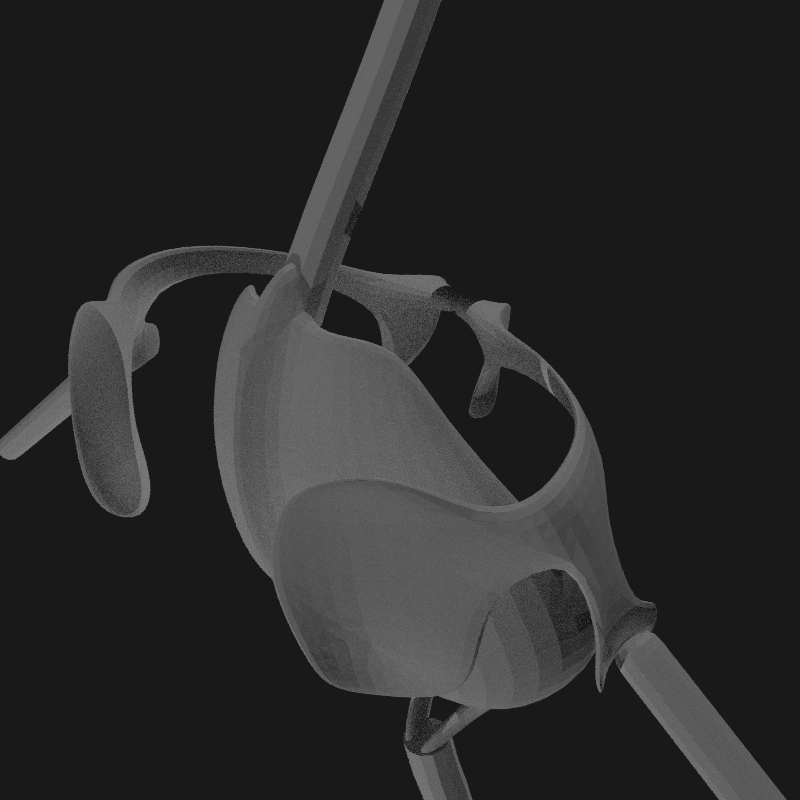
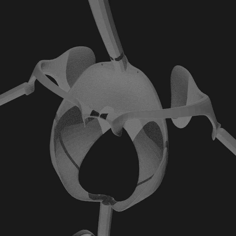
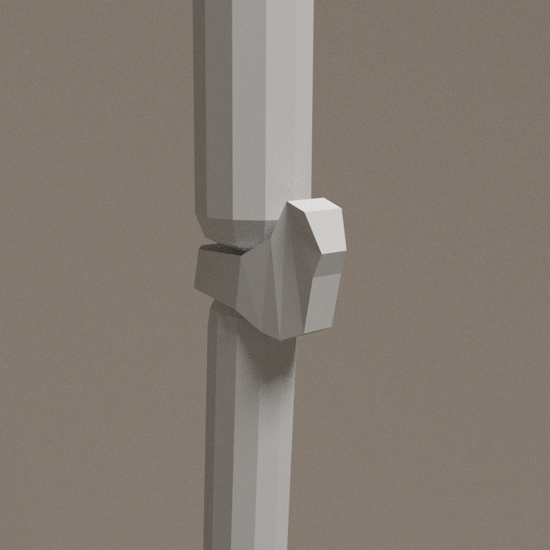
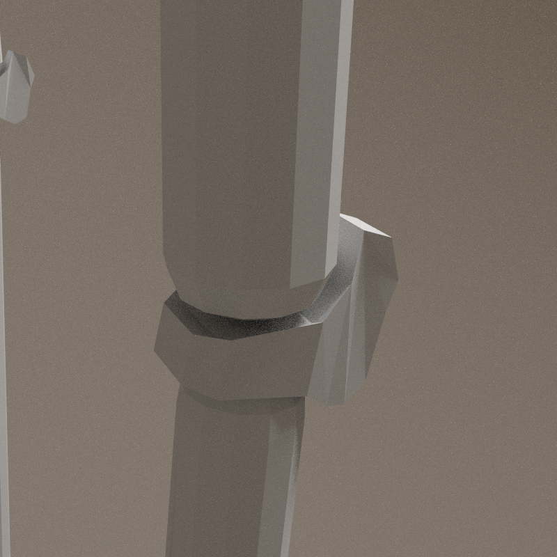
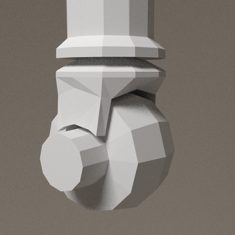
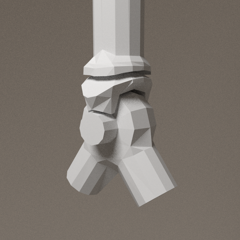
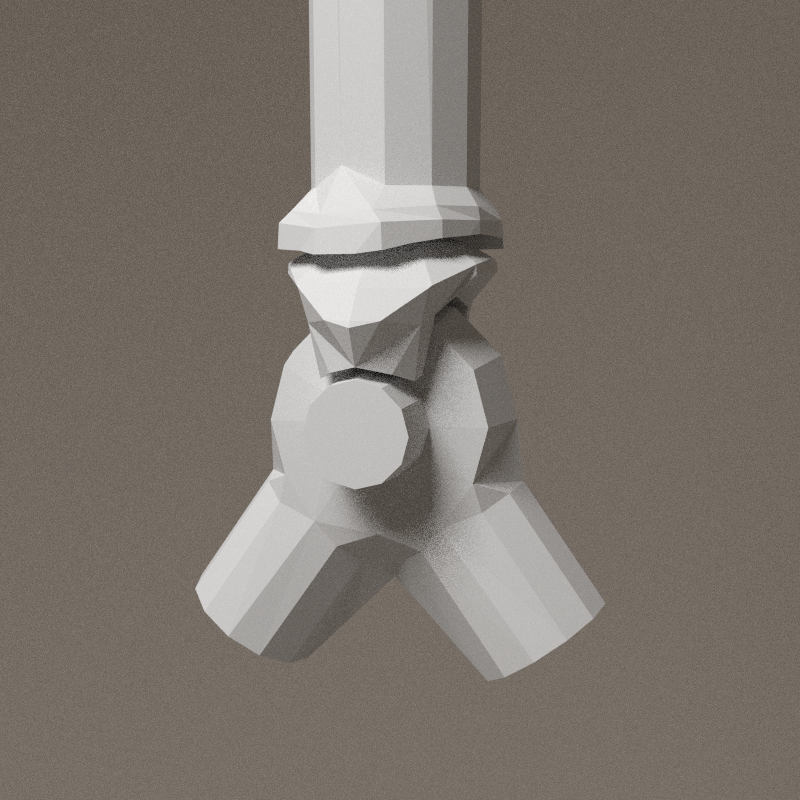
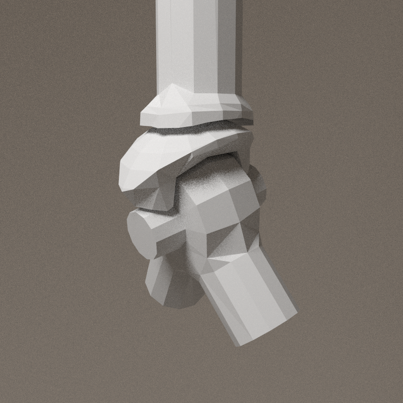
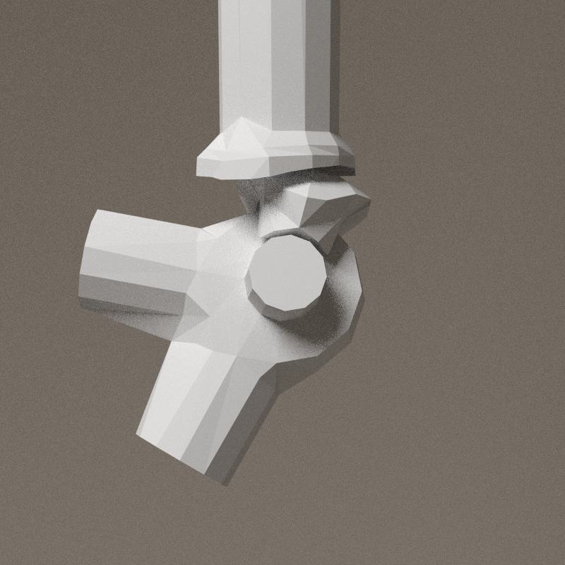
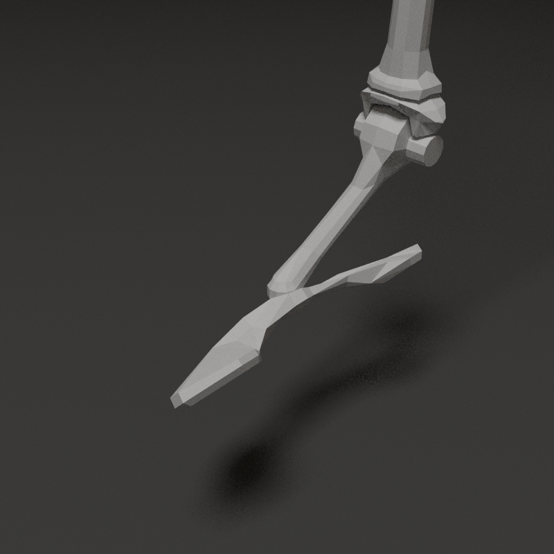
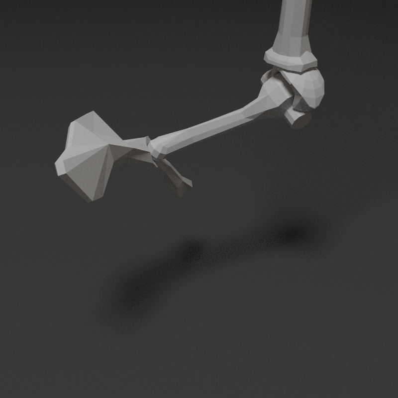
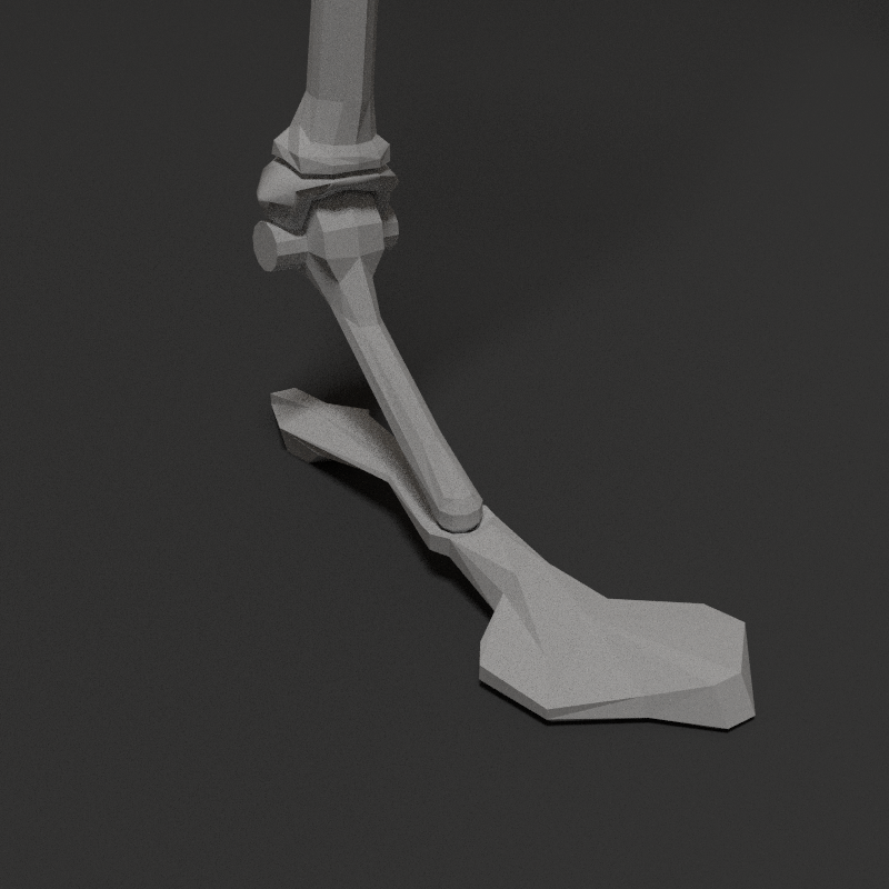
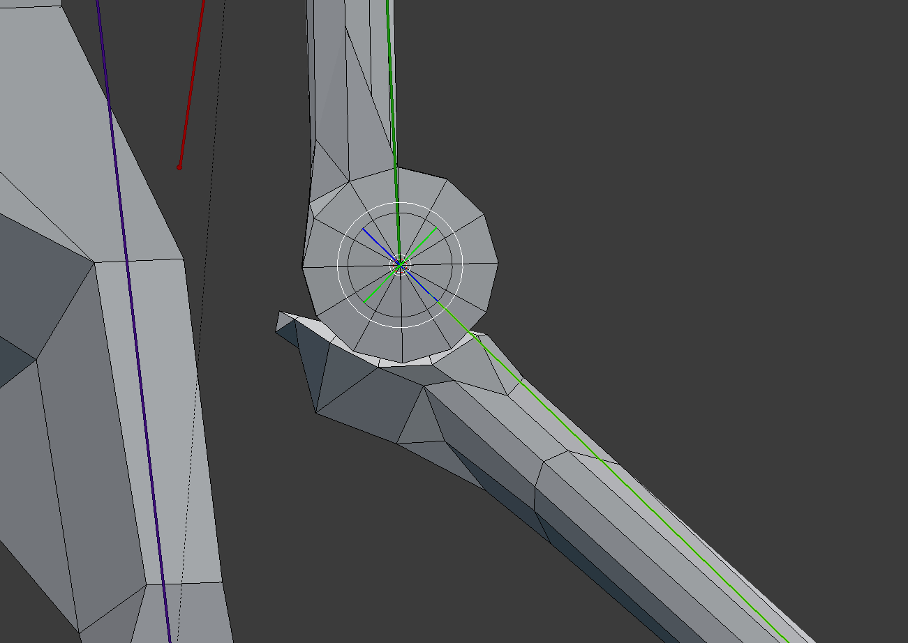
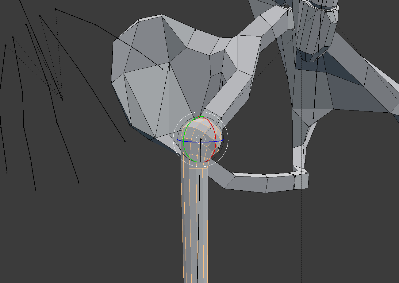
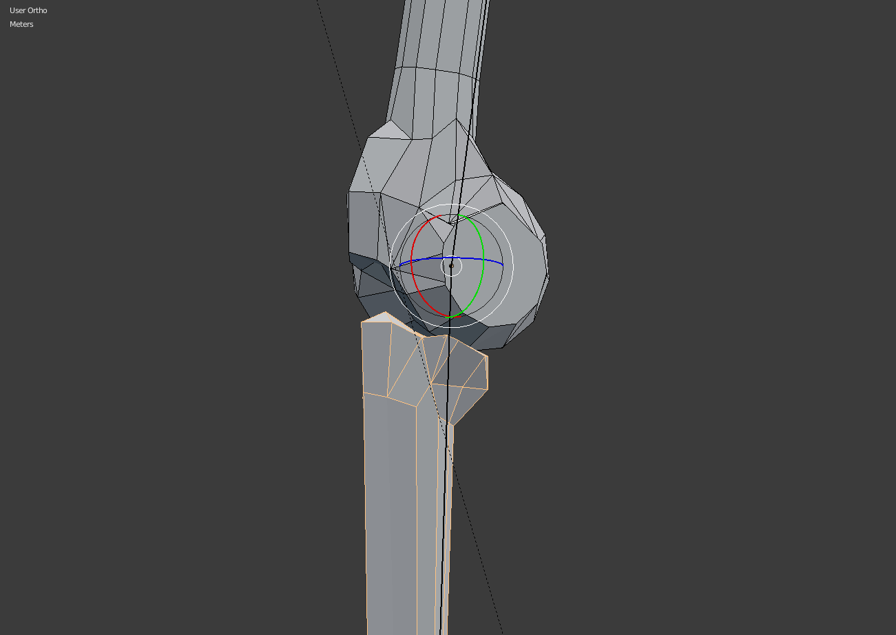
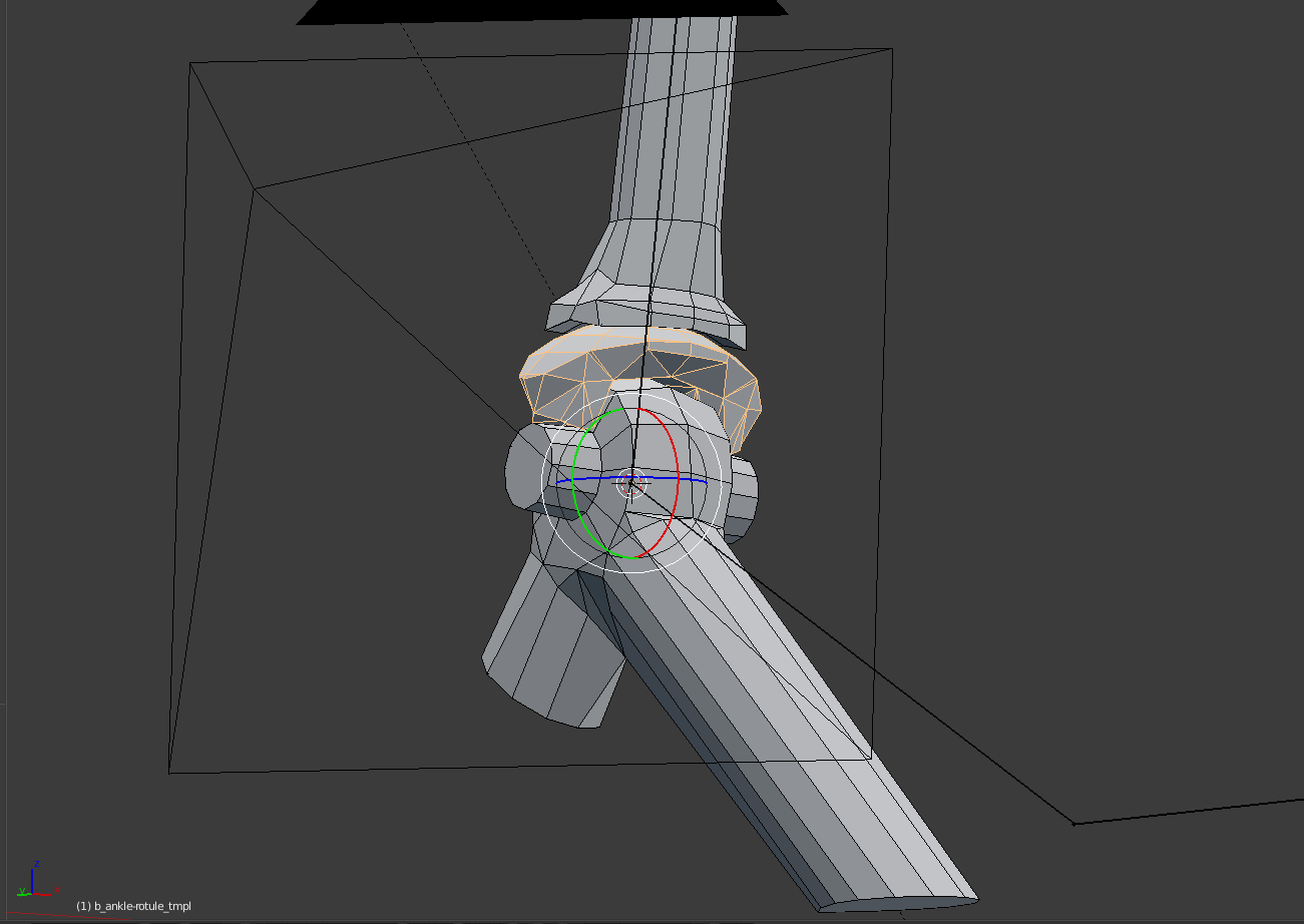
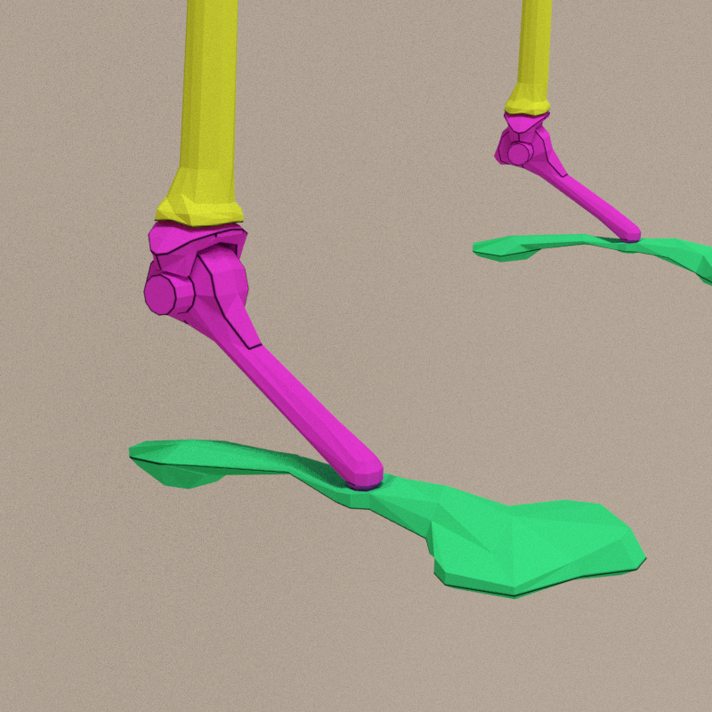
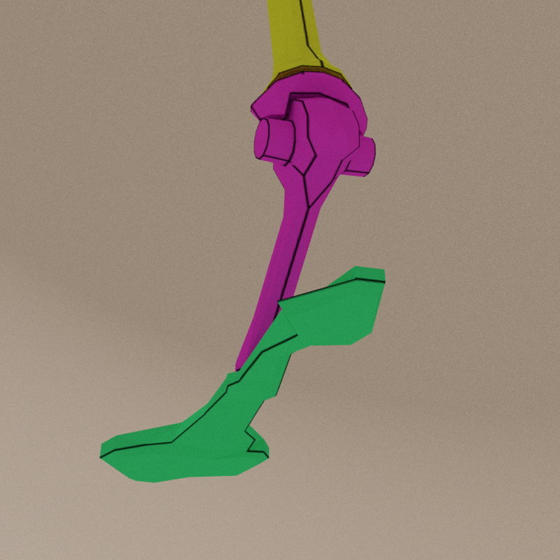
Ankle study
Started as a one axis wheel, it miss a bit of freedom to render the right movments of the ankle. Above the axis, a coupole is cutted, allowing bending of the wheel in Y and Z axis (the wheel turns on X axis). By enlarging the bottom part, the articulation gains in Y axis without becoming huge on the upper part.
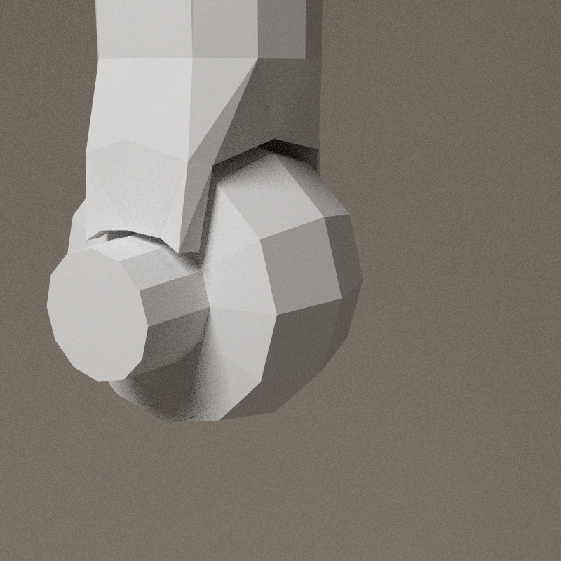

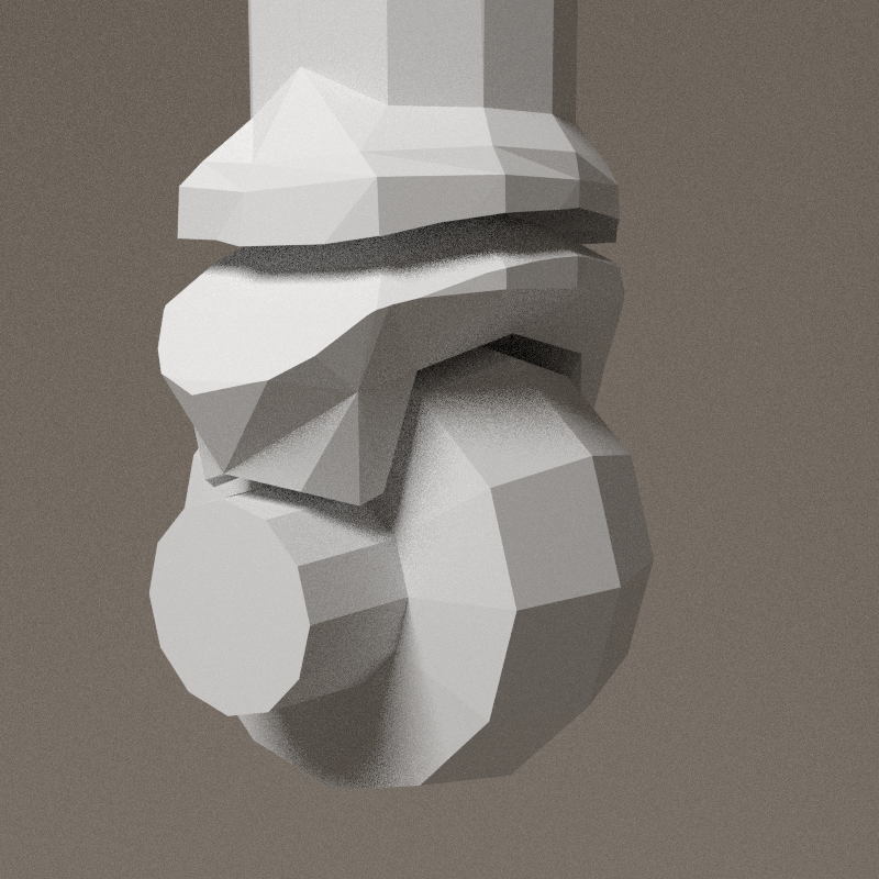
Final version of the articulation, X, Y and Z rotation enabled.
- X: ~ -84° > 84°
- Y: ~ -60° > 60°
- Z: 360°

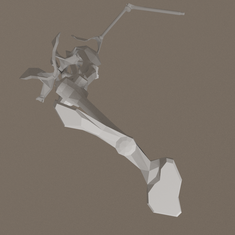
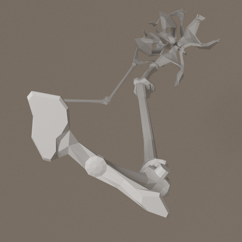
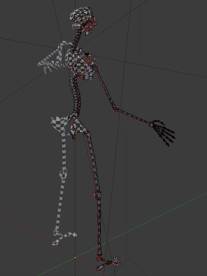
The head and the hand still have to be designed. To test the intergrity so far, i have to place all the bones at the right place. As i'm using the armature of the previous version of the tanukis, members are deformed.
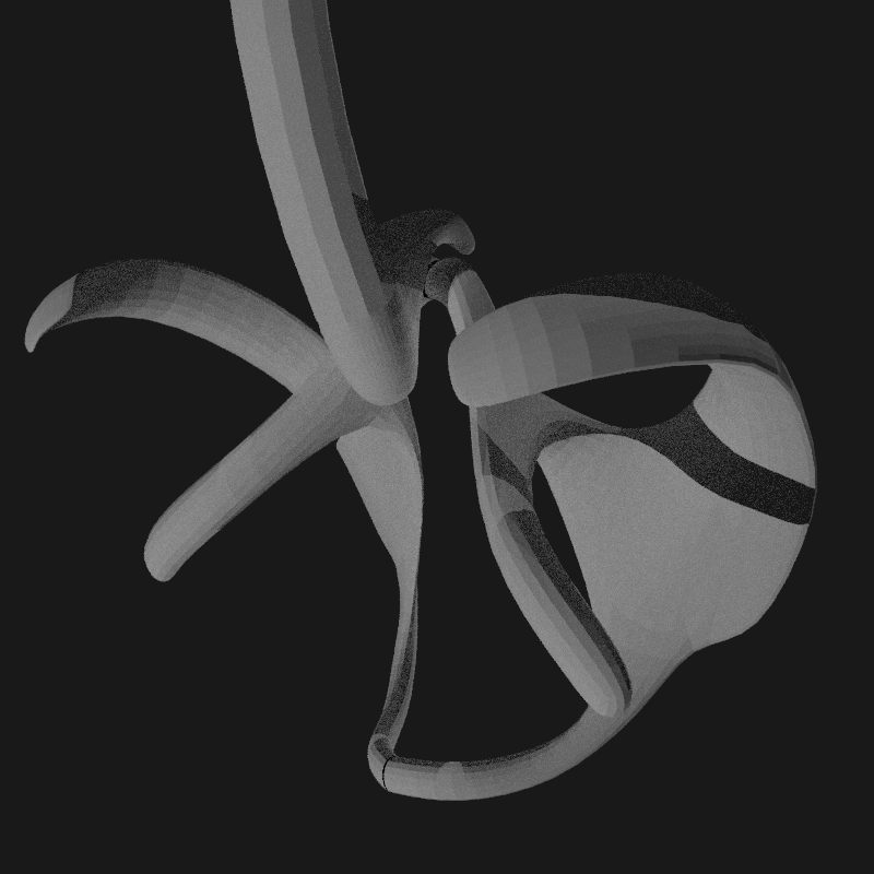
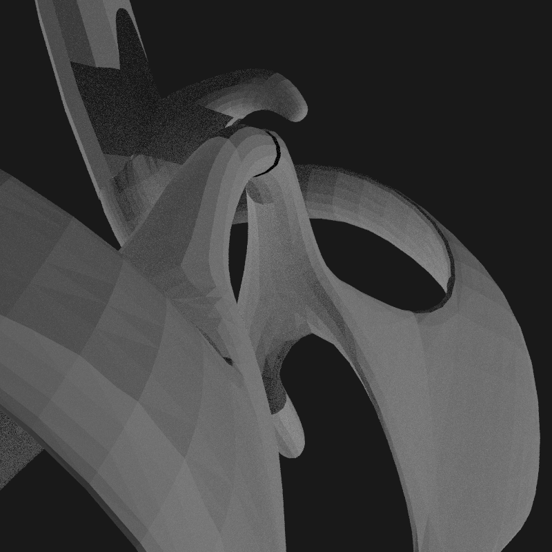
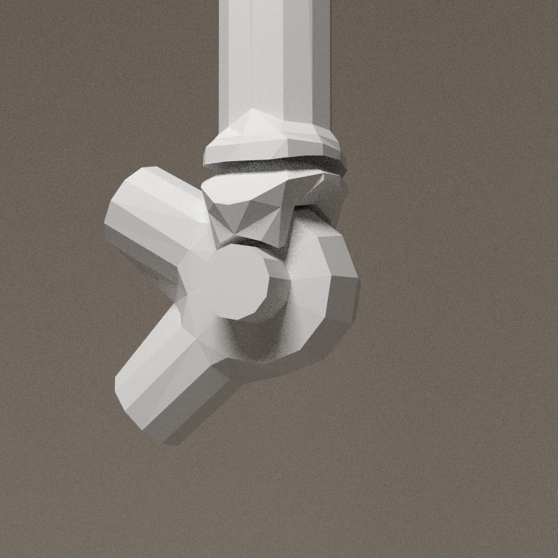
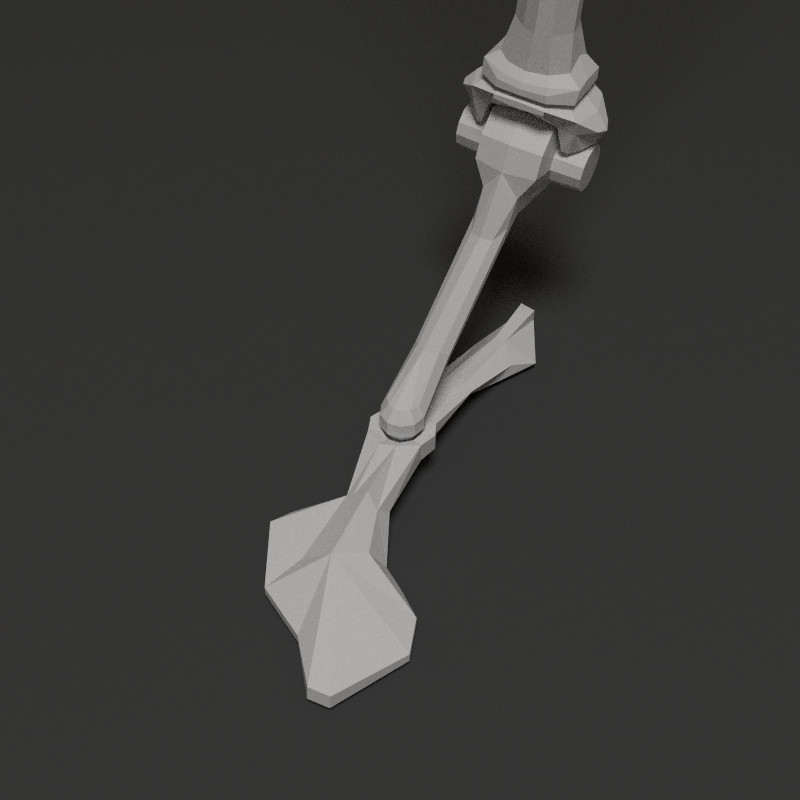
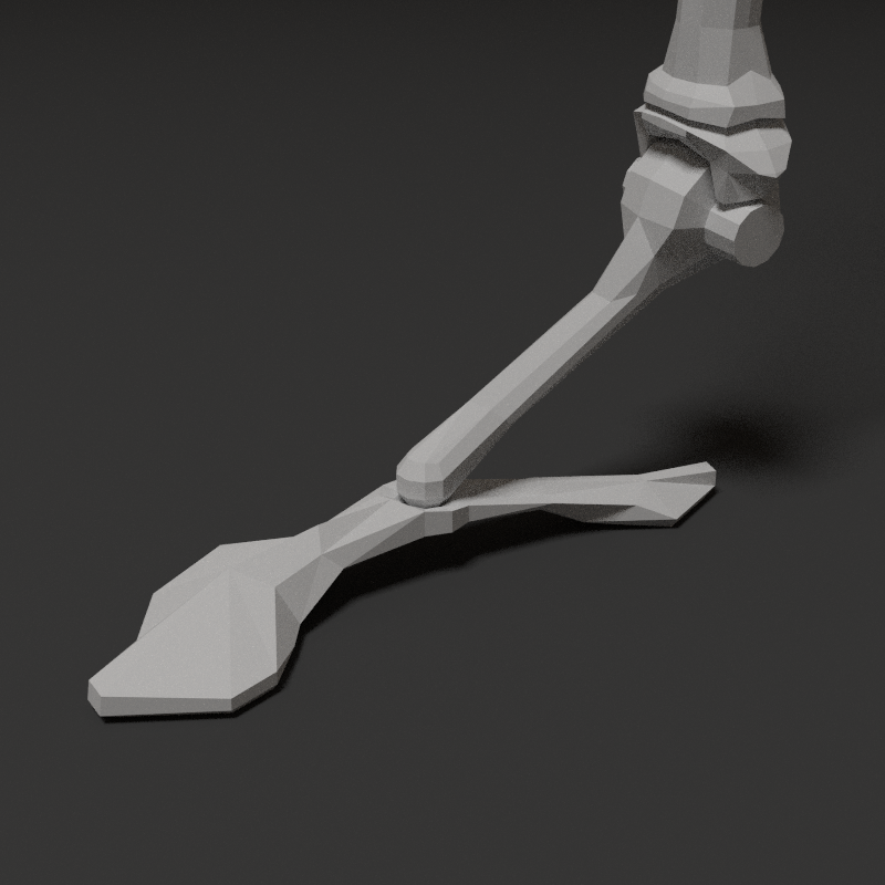
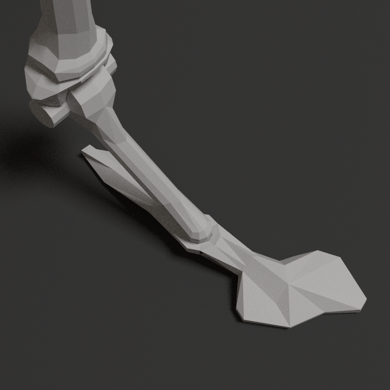
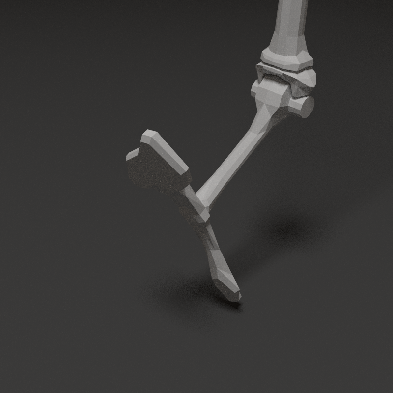
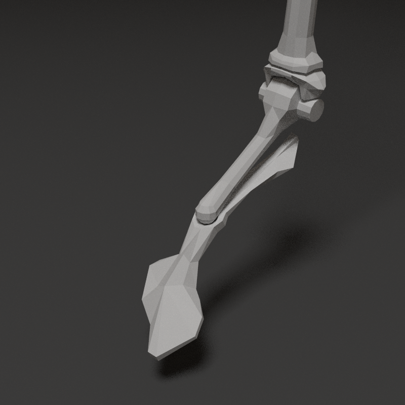
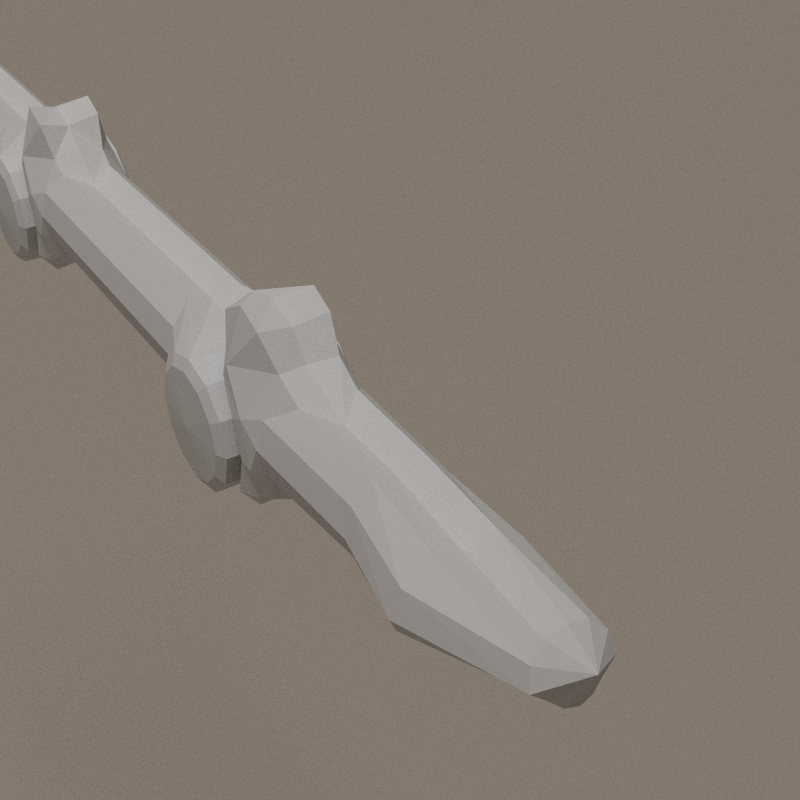
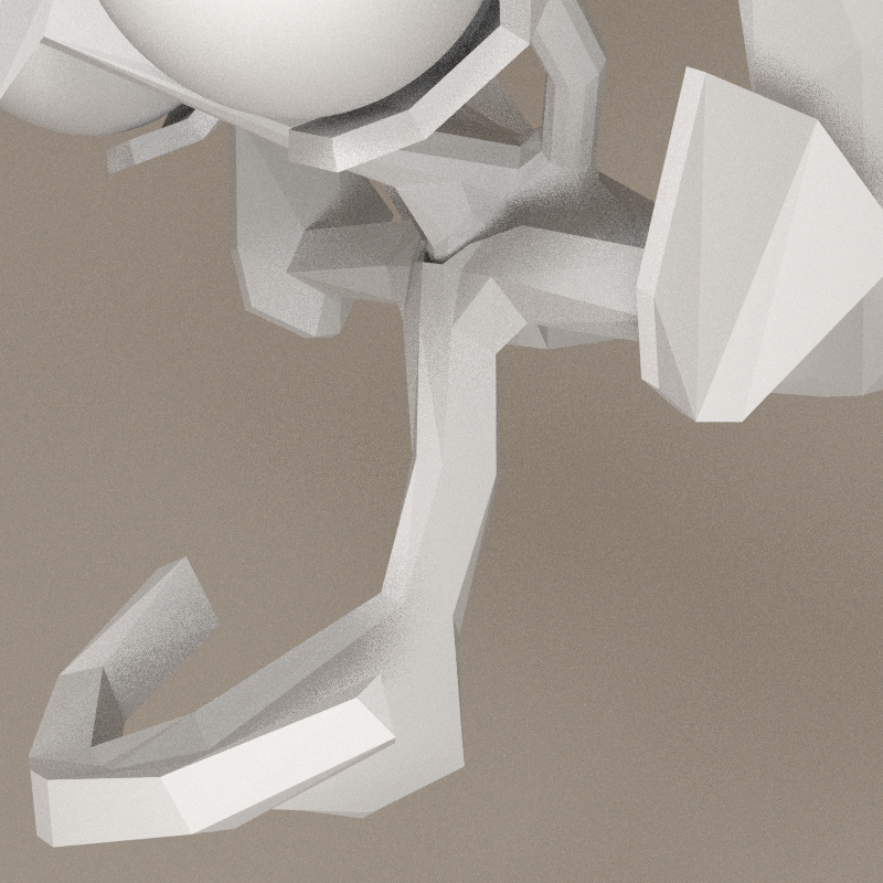
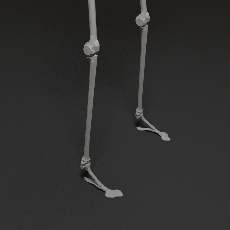
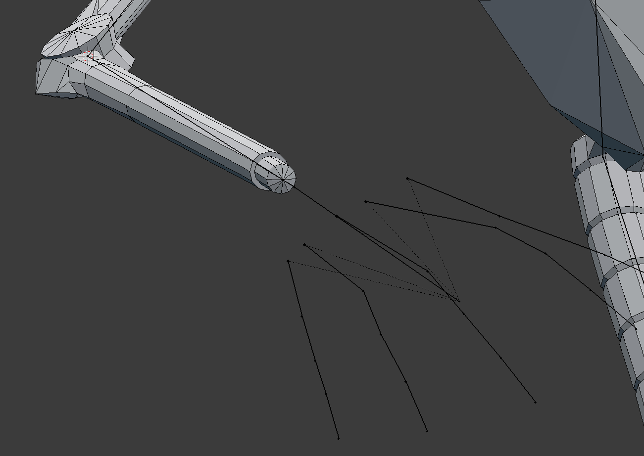
Foot study
After several attempt to end the leg nicely, i designed a foot... Artictulation is a bit special, the heel and toes are fixed together.
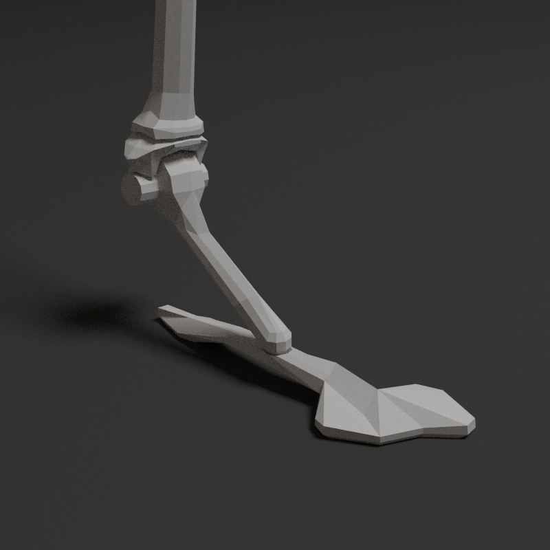


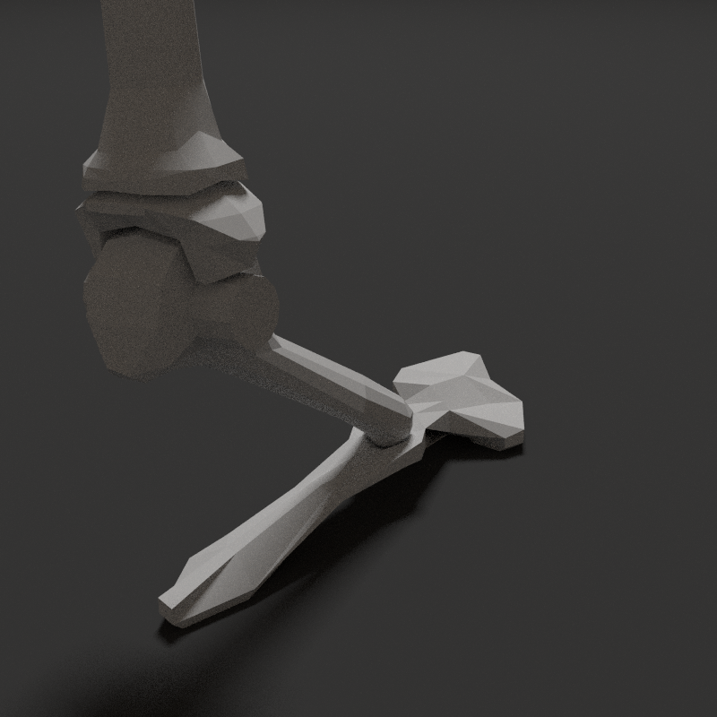
Limits
- X: ~-60° > 32°
- Y: ~-40° > 40°
- Z: 360°
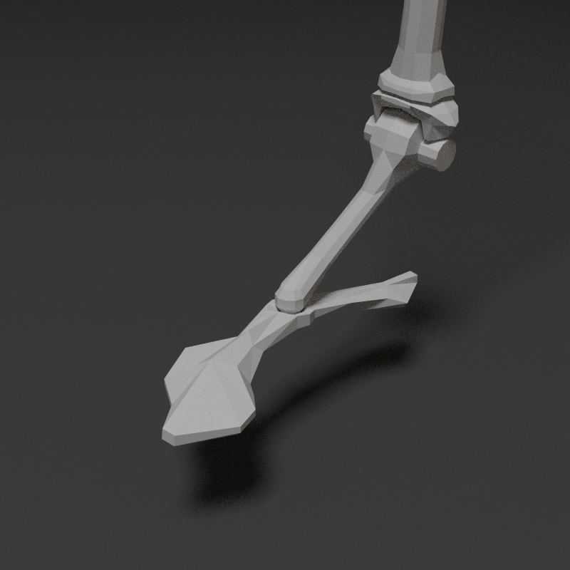

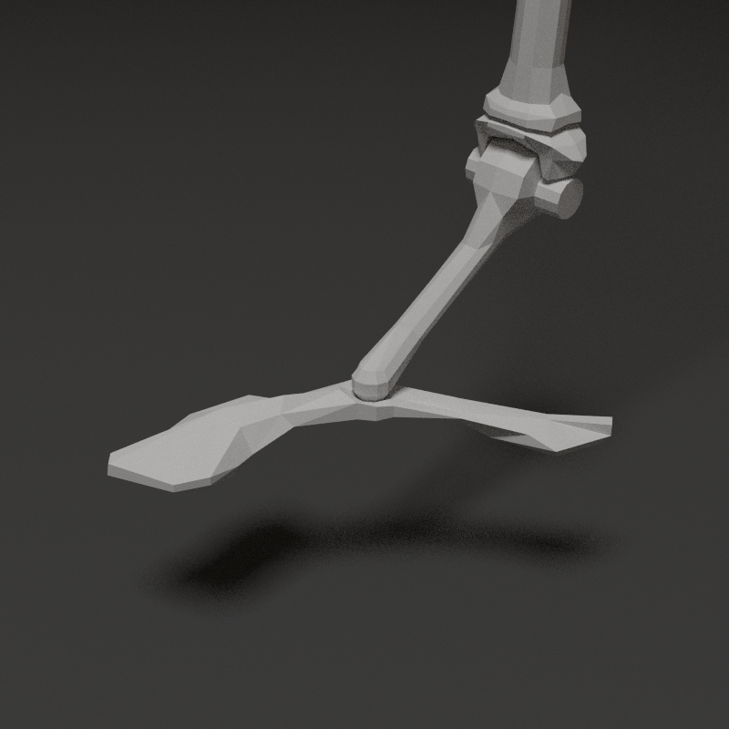
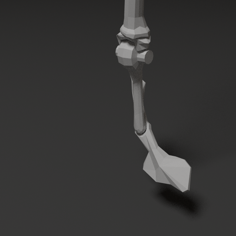
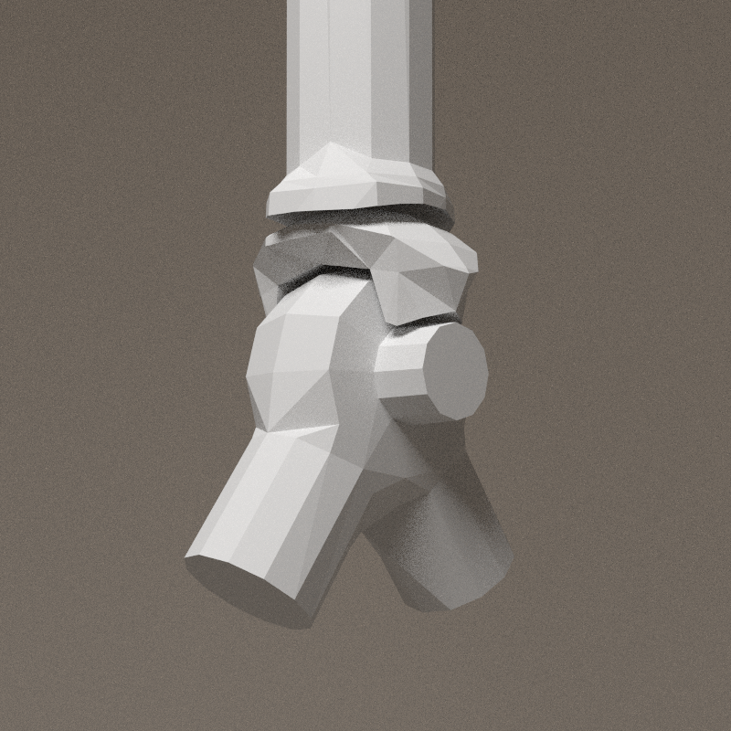
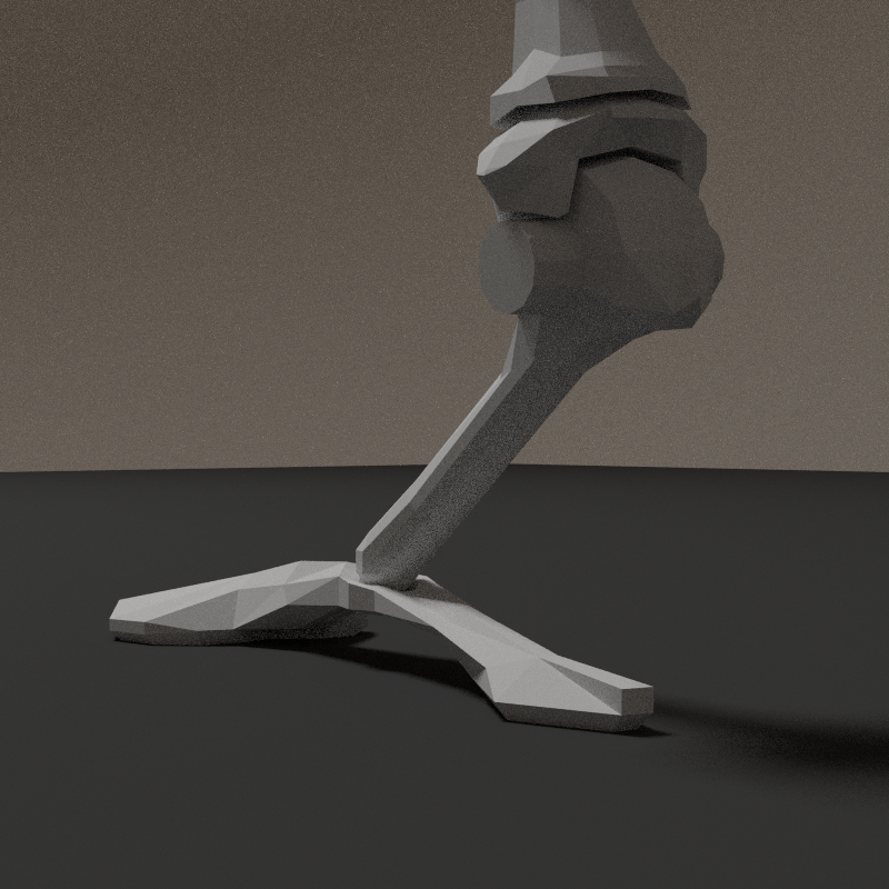
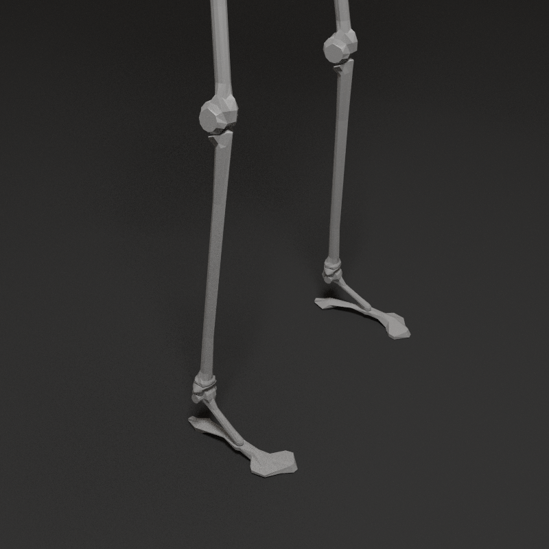
The spherical connection allow foot's plane to adjust to the floor. The result is a kind of sport shoe. I imagine a certain level of elasticity in this bone -> acting as a shock absorber.

With the ankle and the foot articluation, the foot is very agile.
Note


Strange to realise the similarity between my design of an avatar's foot and the Hugh Herr[1]'s one. The foot's arch is also designed as a spring. Maybe I saw that once, it was in an hidden place in my mind and influenced my research... There's a clear relation even if I'm not certain of the idea's genealogy.
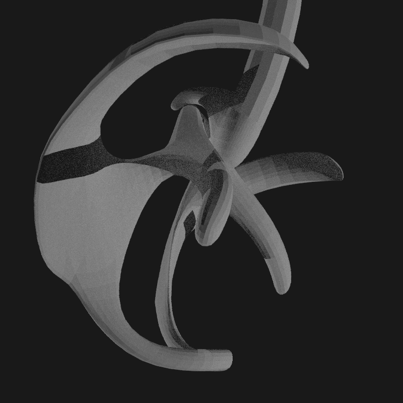
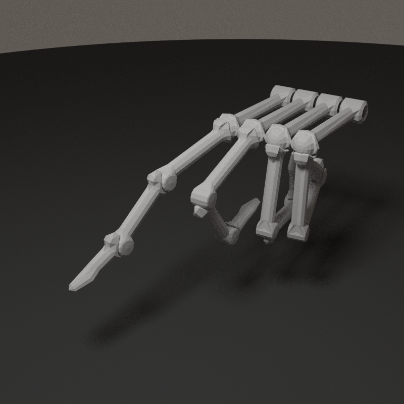
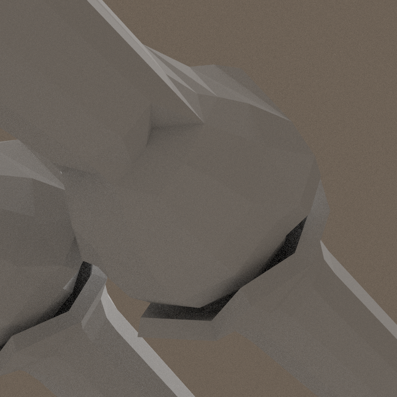
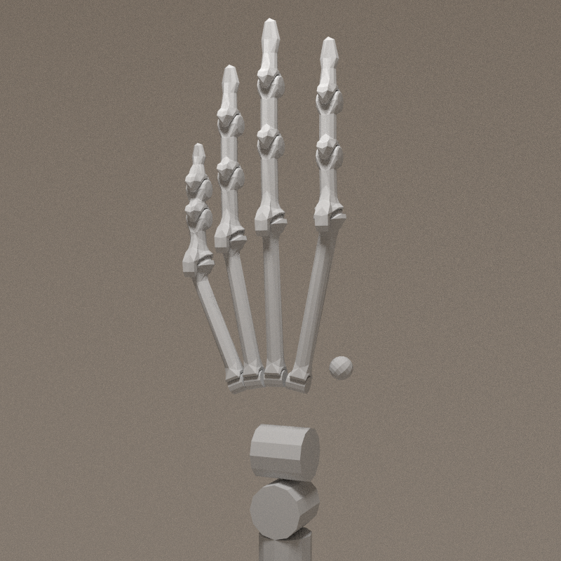
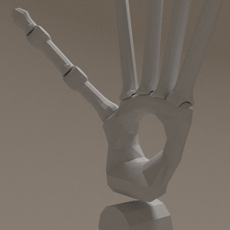
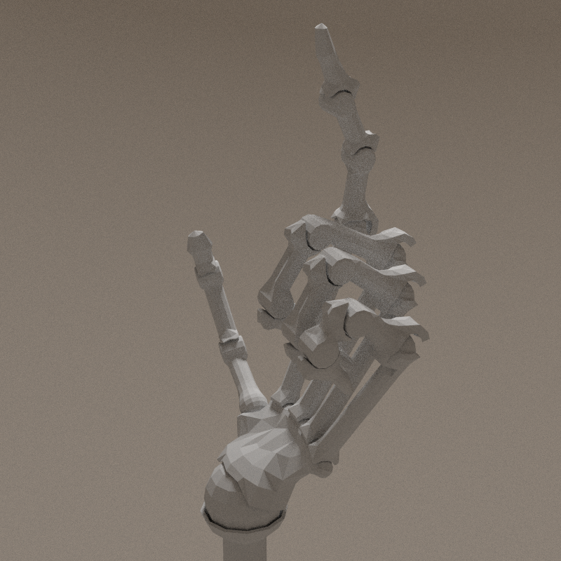
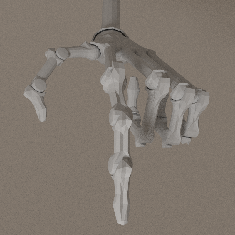
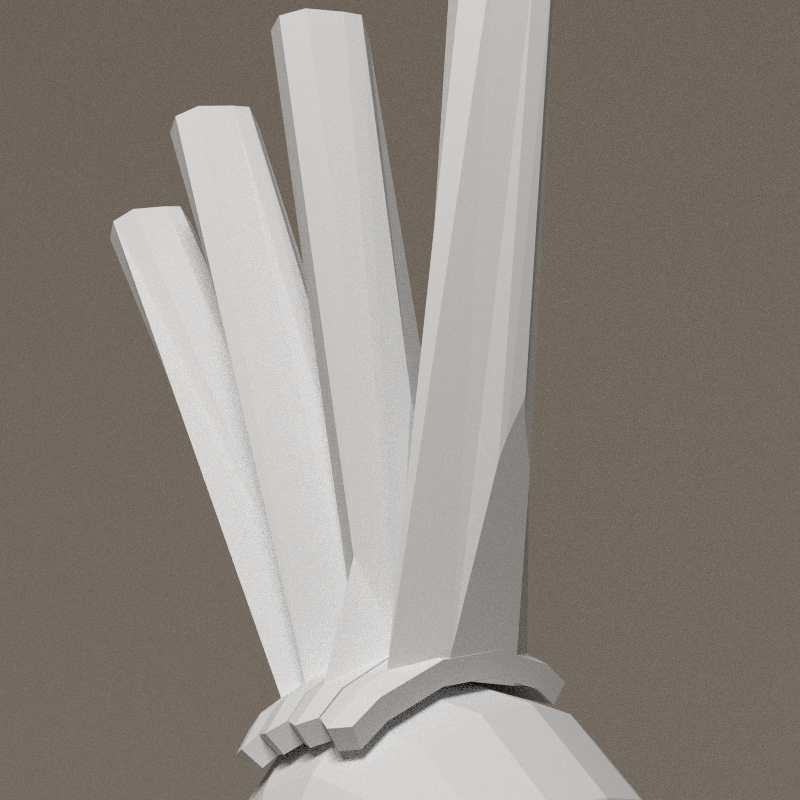
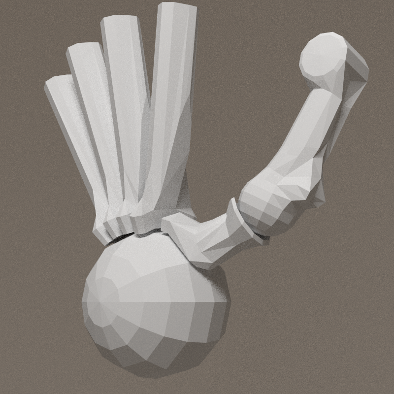
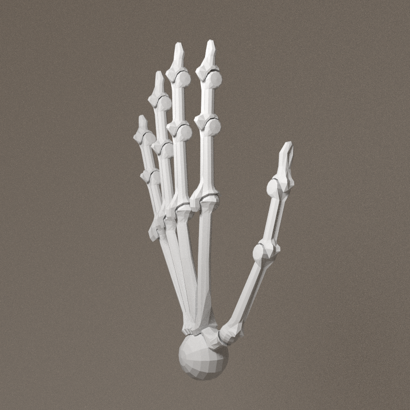
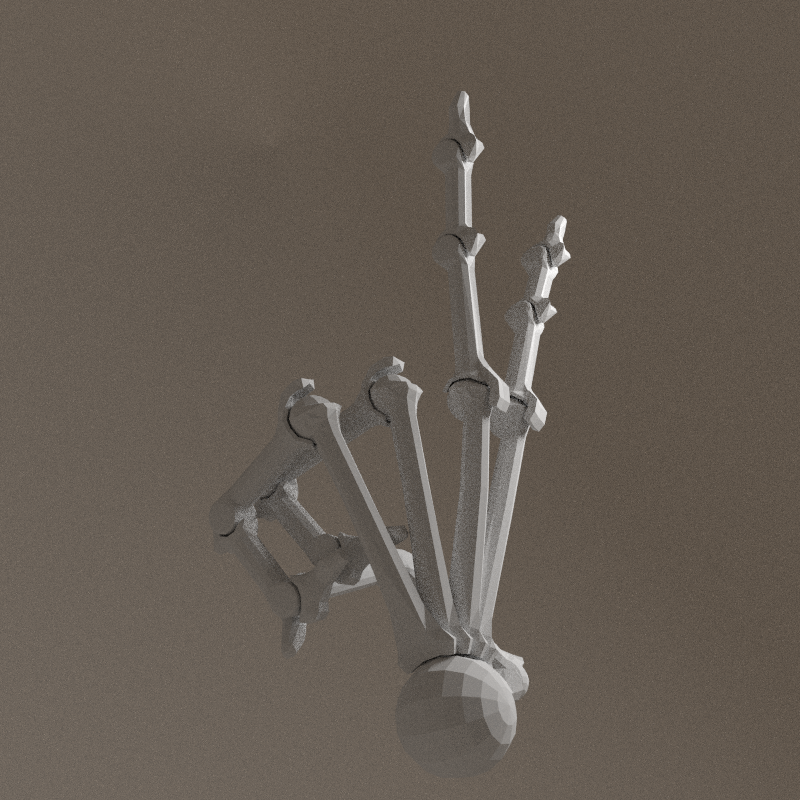
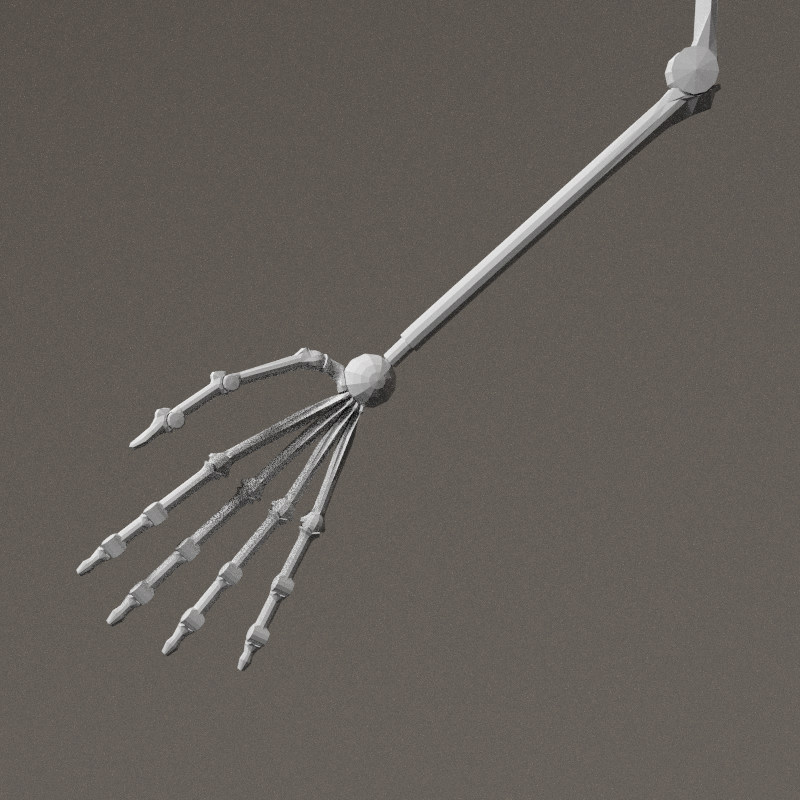
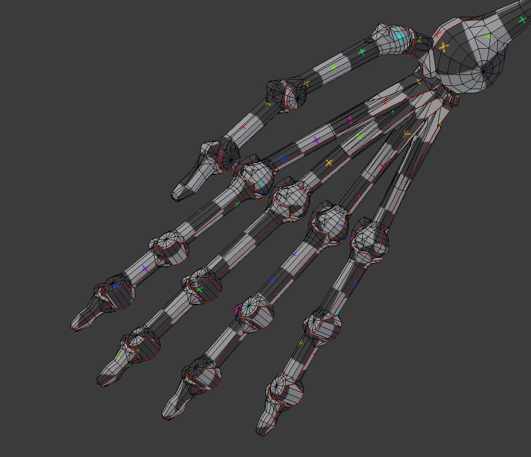
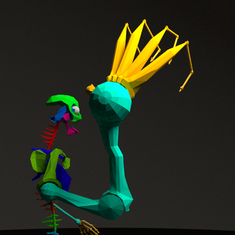
Hand study
This part is a tricky & scary one. First researches have been done on in another context, with the palm divided in 5 parts.

It's a very complex part of the skeleton, especially because it will be one of the major physical interaction point in the installation. I like bionic style, but it's not consistant with the rest of the skeleton. Another question is: will the hand be cover by skin, or is it directly the final surface? With tendons visibile, an "écorché" hand. The foot is a nice mix of bones & cyber.
Workspace:

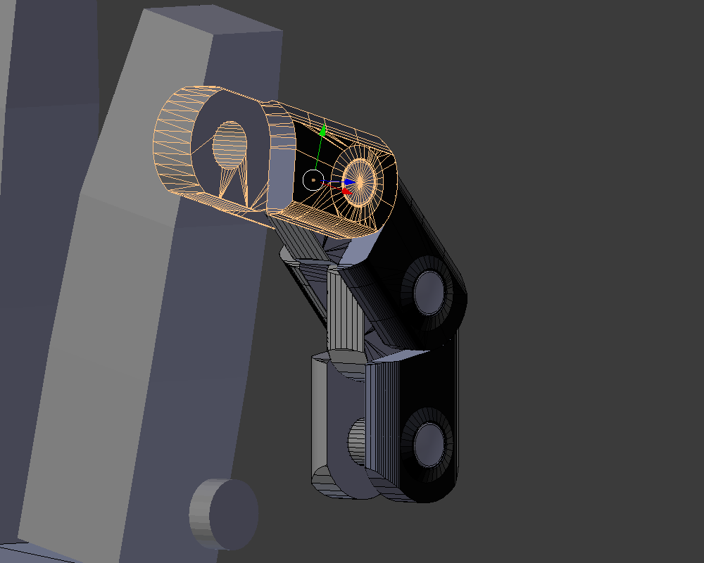
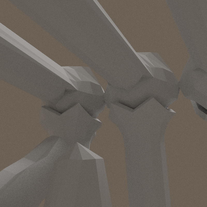
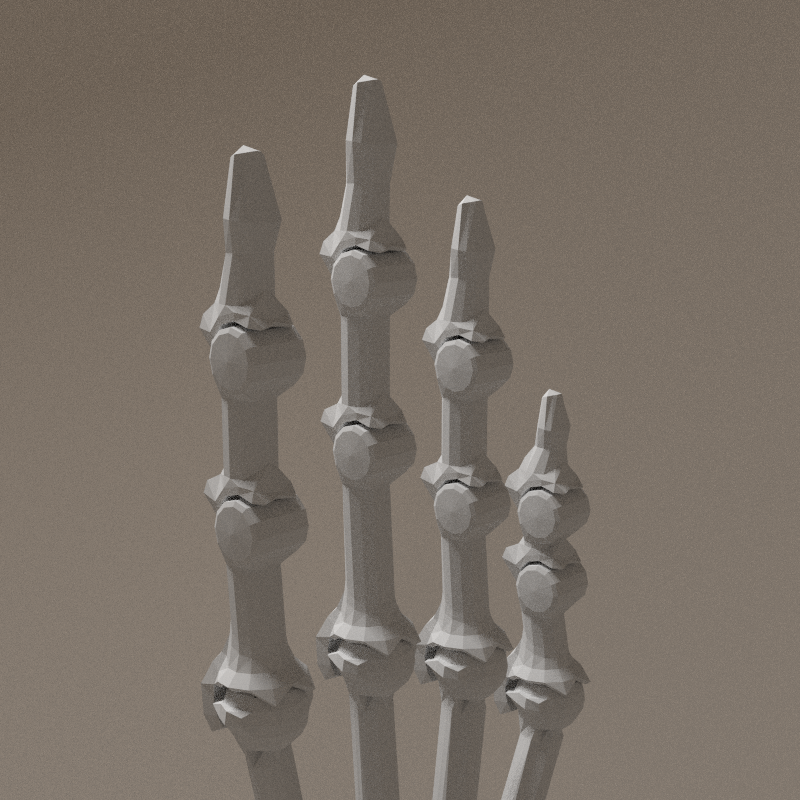
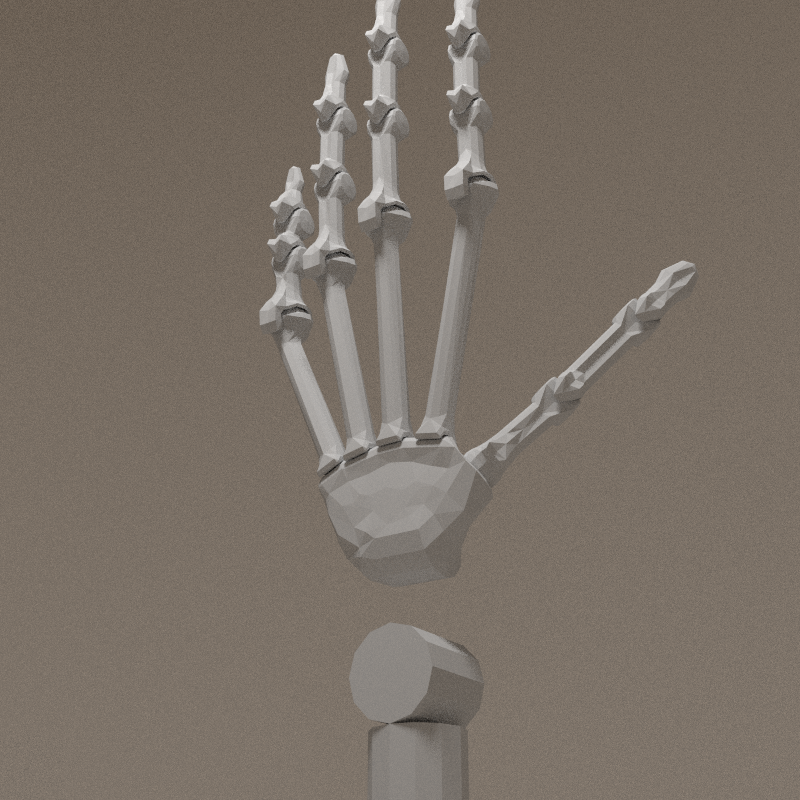
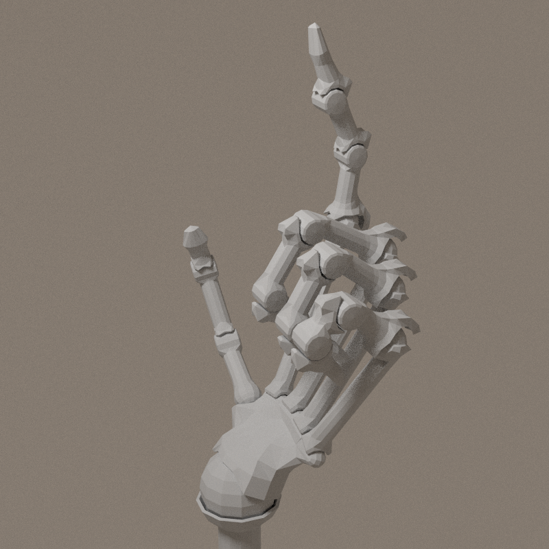
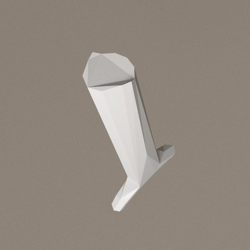
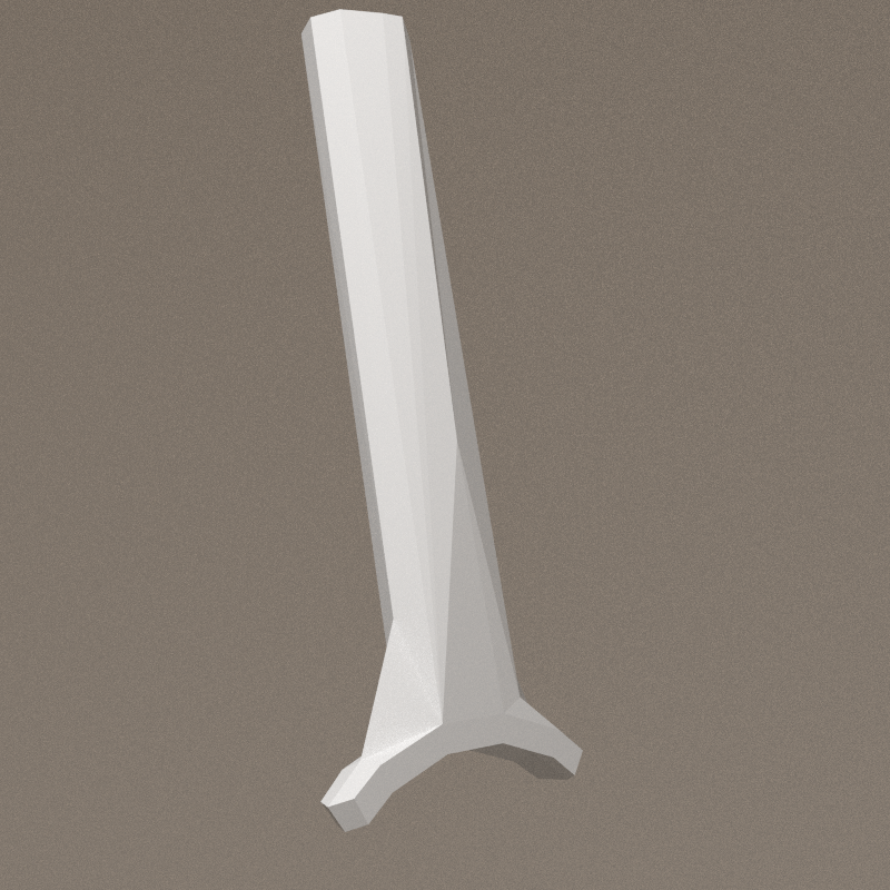
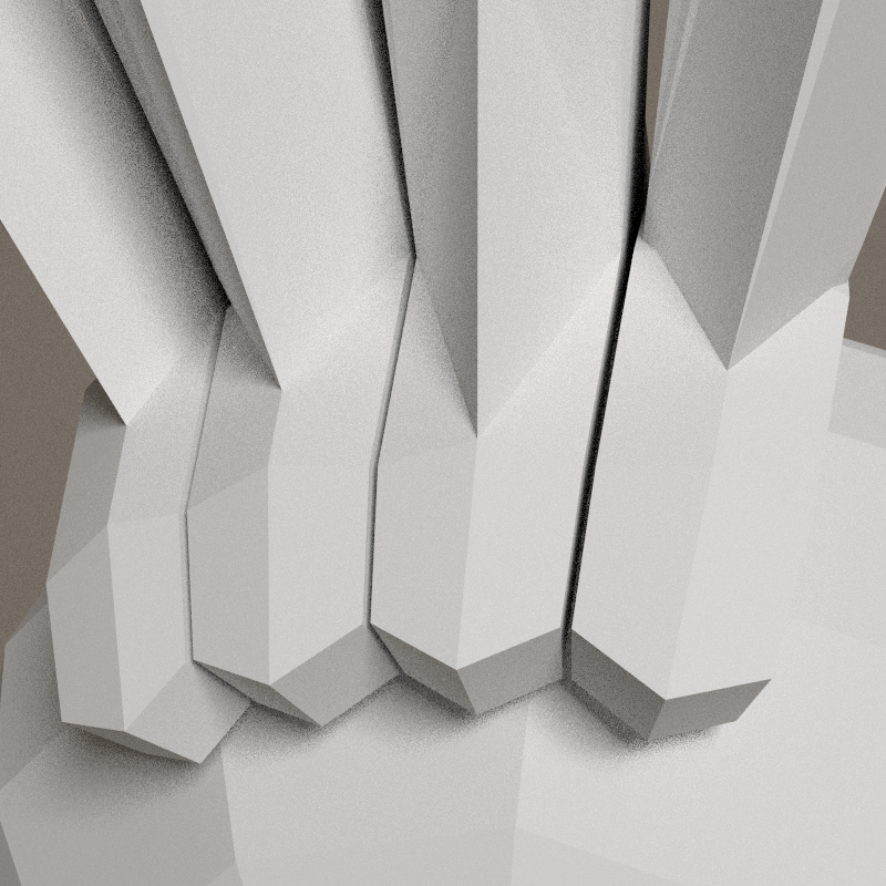
Finger

source: http://www.learnbones.com/hand-bones-anatomy/
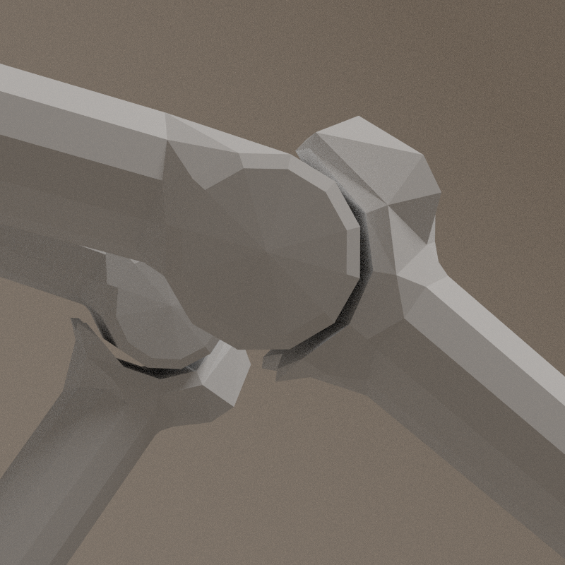
- metacarpals are fixed in one row, strong constrain on X axis
- proximal phalange - spherical articualtion with bumpers
- X axis: ~ -103° > 17°
- Y axis: ~ -19° > 19°
- intermediate phalange - cylindrical articualtion
- X axis: ~ -120° > 20°
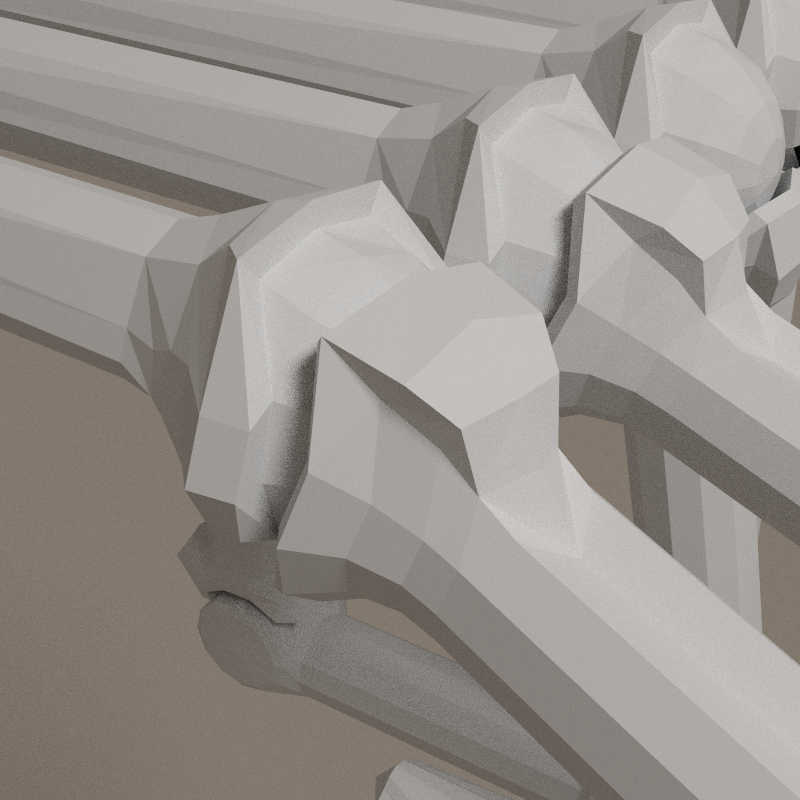
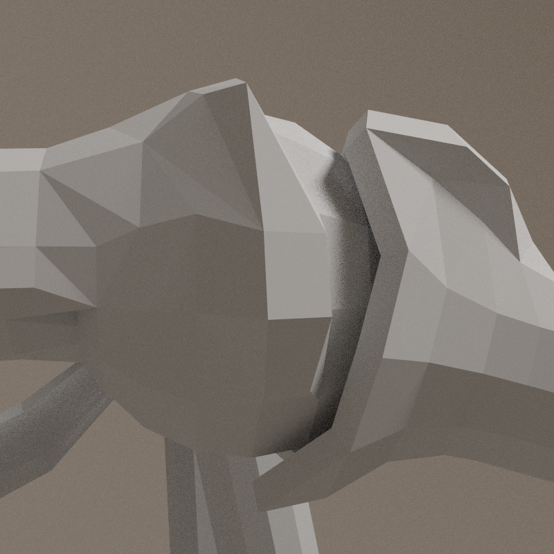
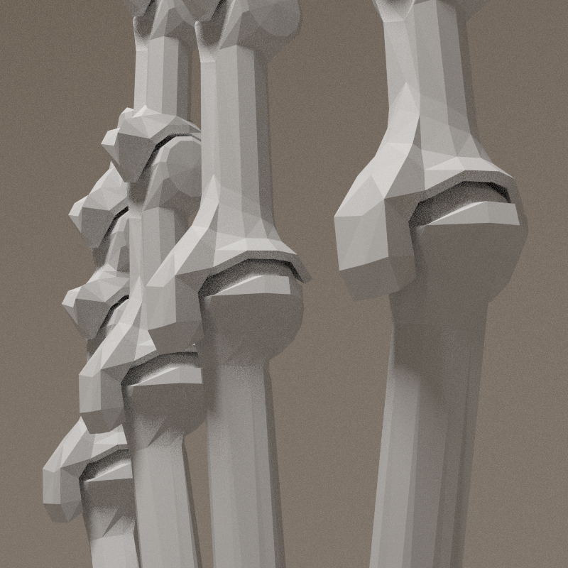
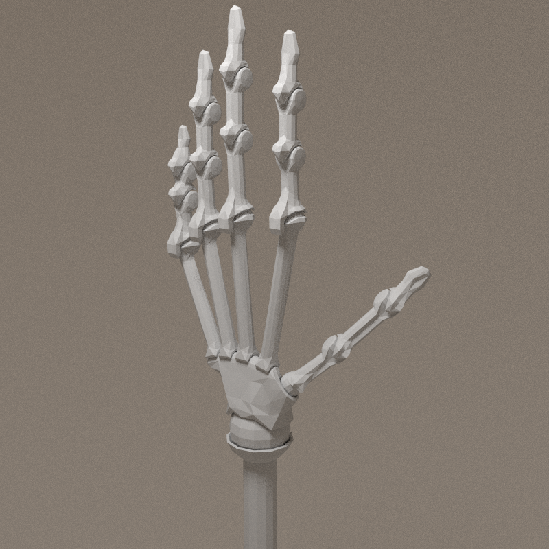
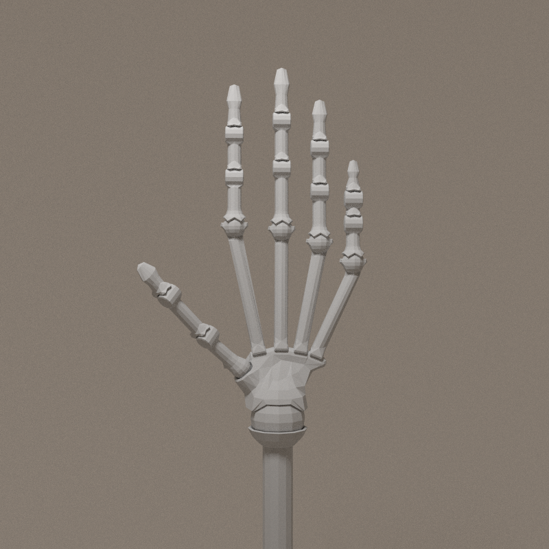
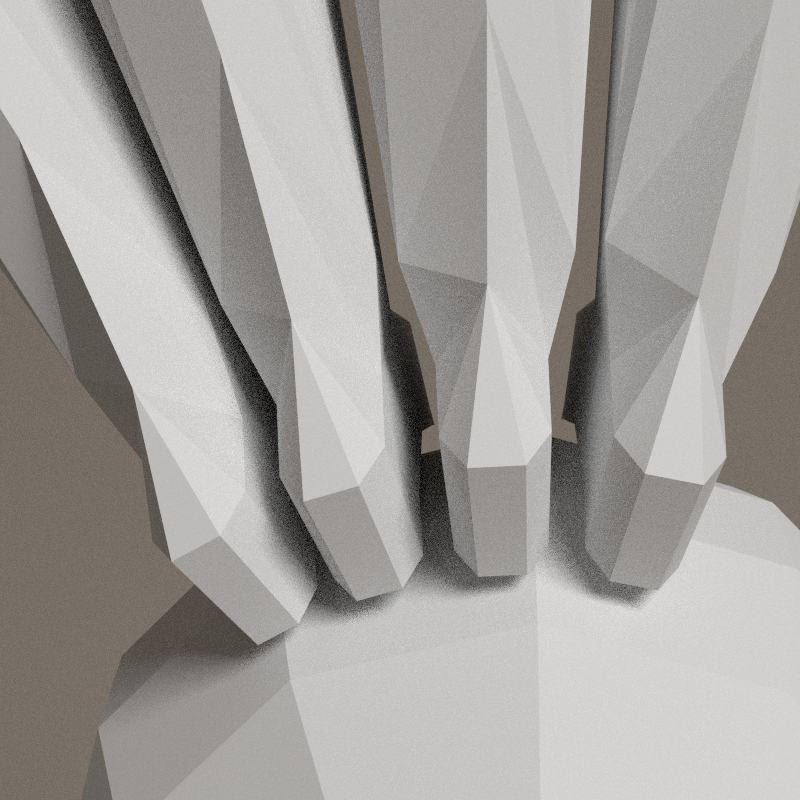
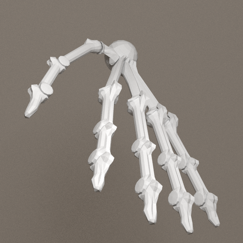
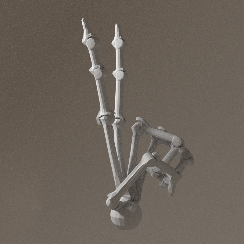
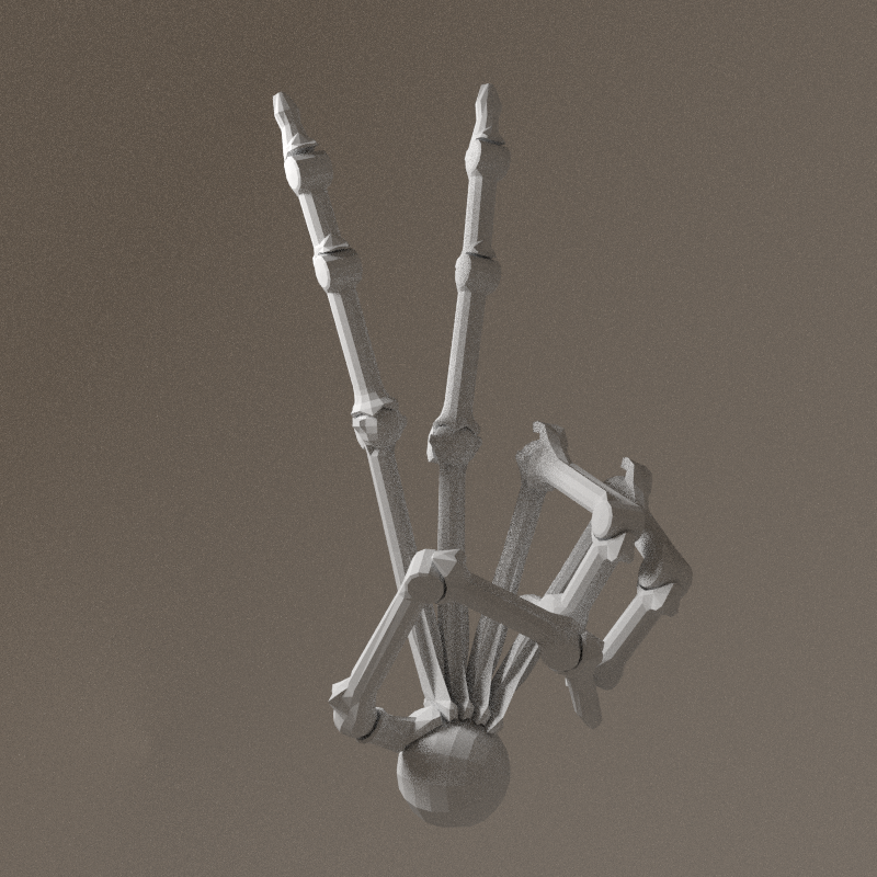
the three last images are an improved version:
- all tuberosities have a valley in the middle for tendon
- the metacarpal to proximal phalange articulation's protection is ensured by the tuberosity, a kind of shield


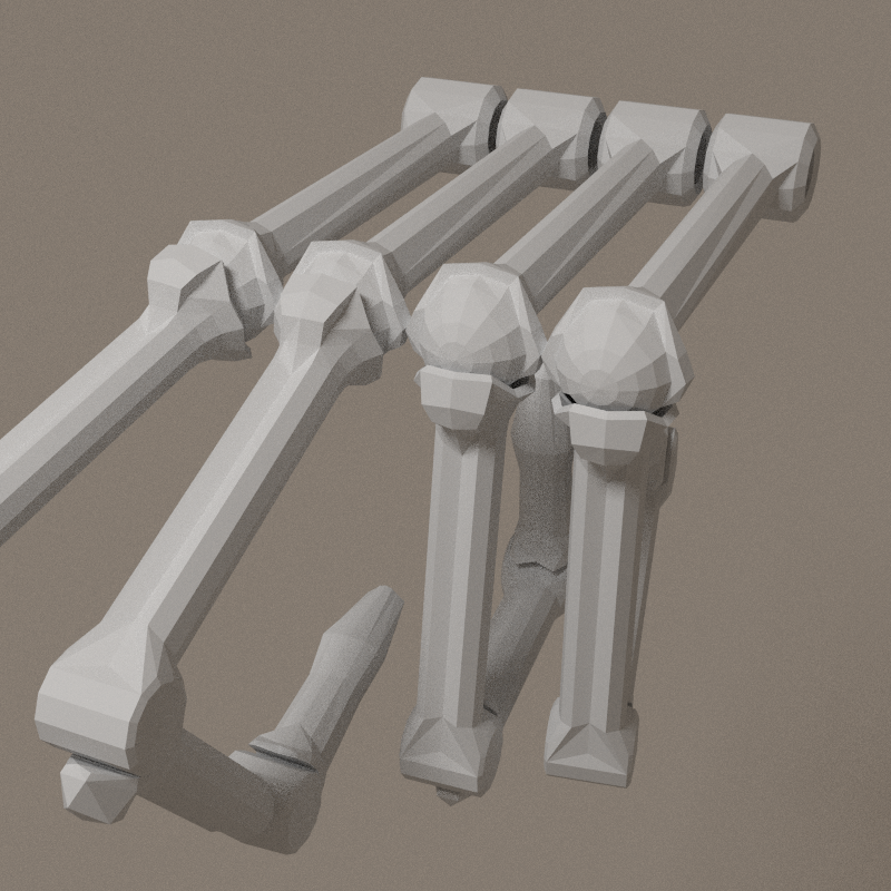
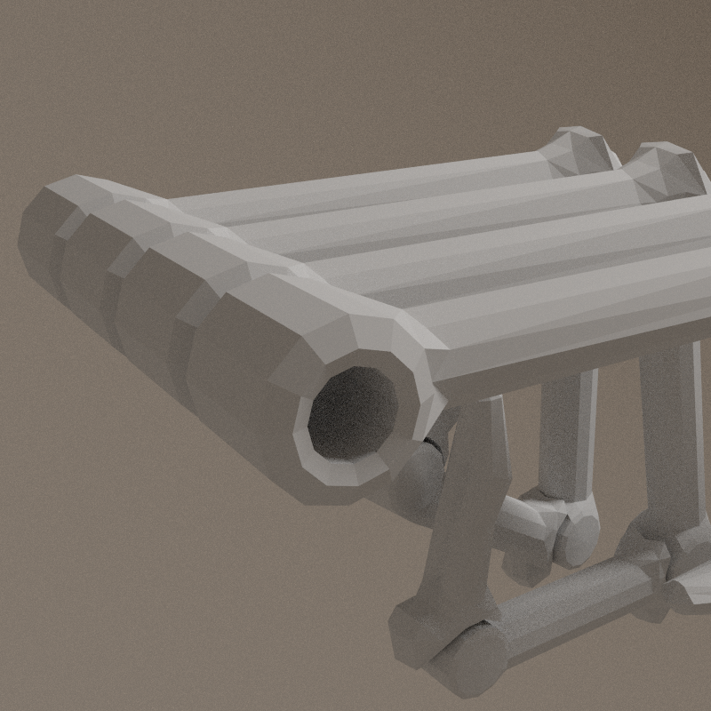

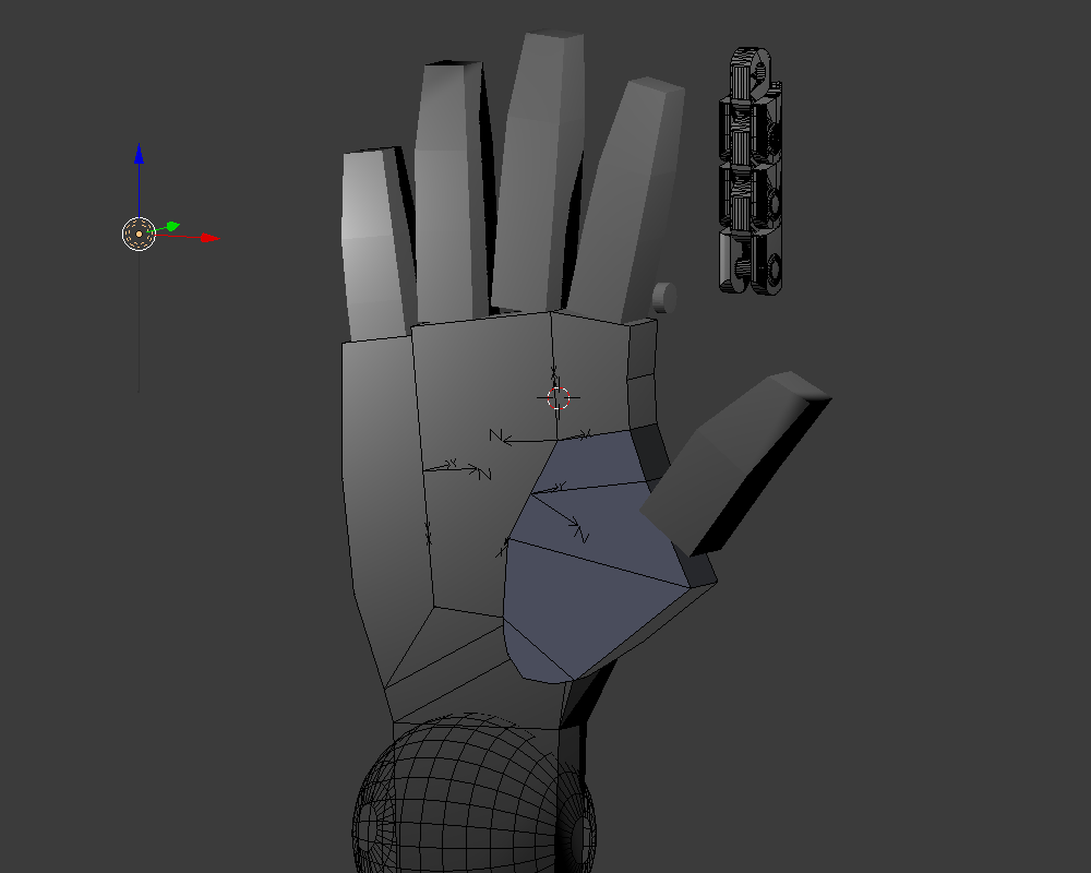
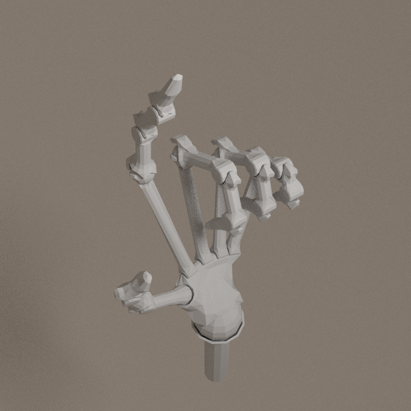
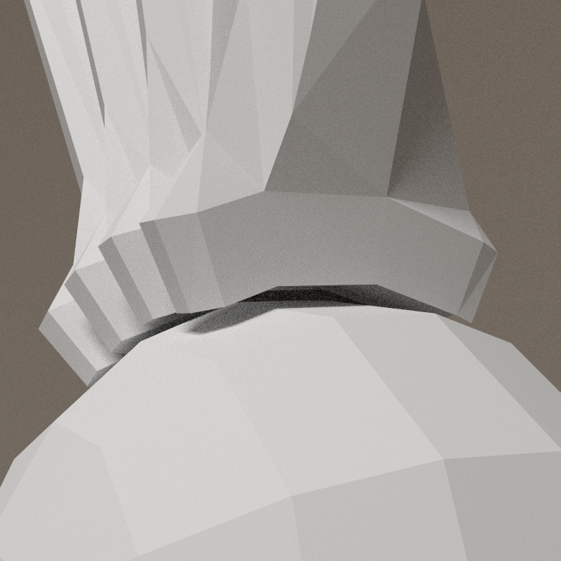
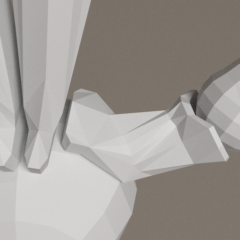
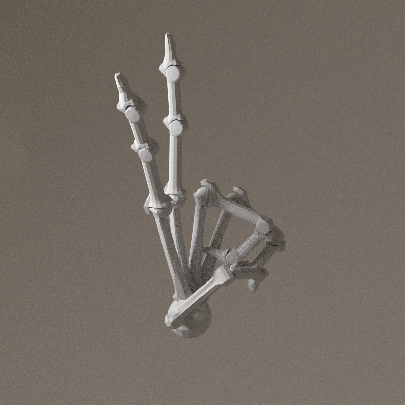
Palm
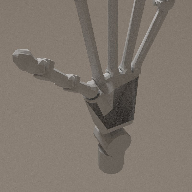
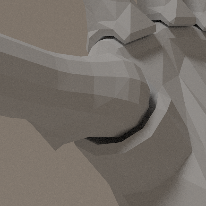
Back to documentation: wrist is a complex articulation. I can't summarise mentally the juction with fingers & the articulation with the forearm. Spherical joint and cylindrical ones, in a so tiny space!
I need 3 axis of freedom at the wrist and 1 for each finger metacarpal, and 2 for thumb's metacarpal. One of the axis of the wrist will be ensured by the connection to the forearm ( see elbow study ). The hand is not very flexible in the perpendicular axis of the palm - adbuction/adduction[2] -, this joint will come at the sceond place. The third one - flexion/extension - will have the shape of a cylinder and connect to a carpal bone were all the metacarpal bones will be connected. It's shape will be odd as it will be composed of half of a cylinder, a spherical hole ( to thumb ) and 4 half of cylinder, with different orientations ( to fingers ). Let's design this!
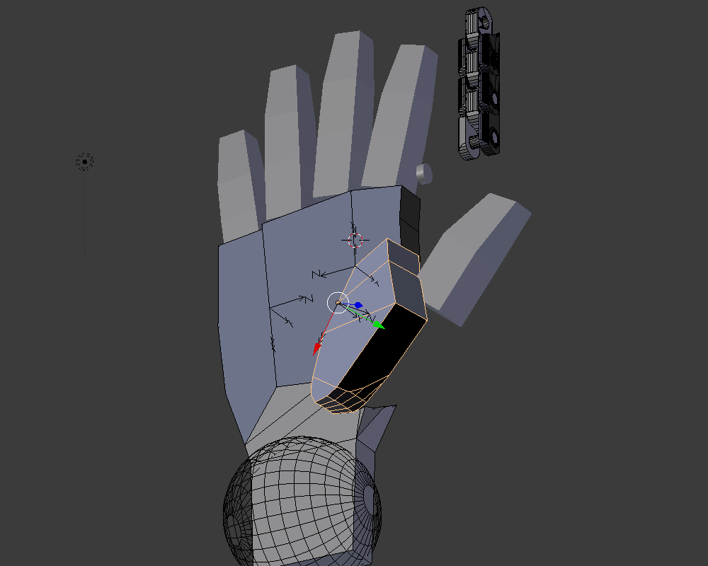
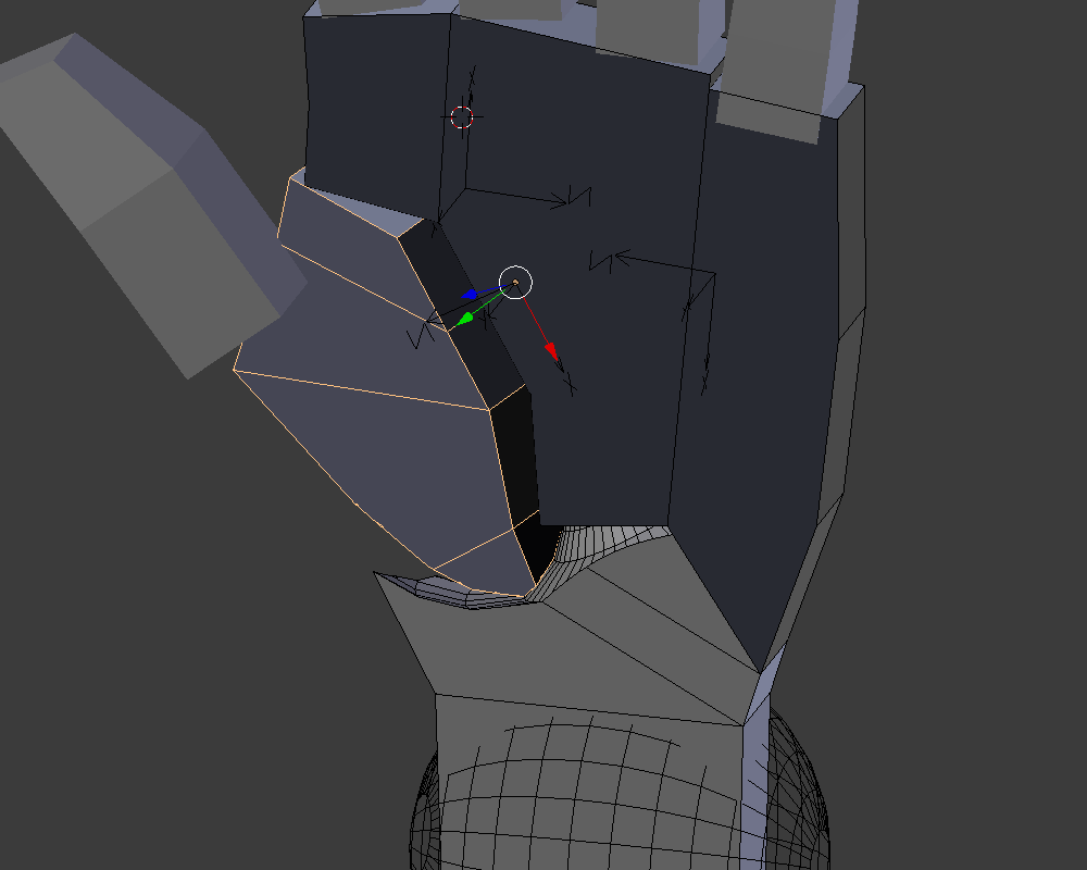
Adjustment of the fingers


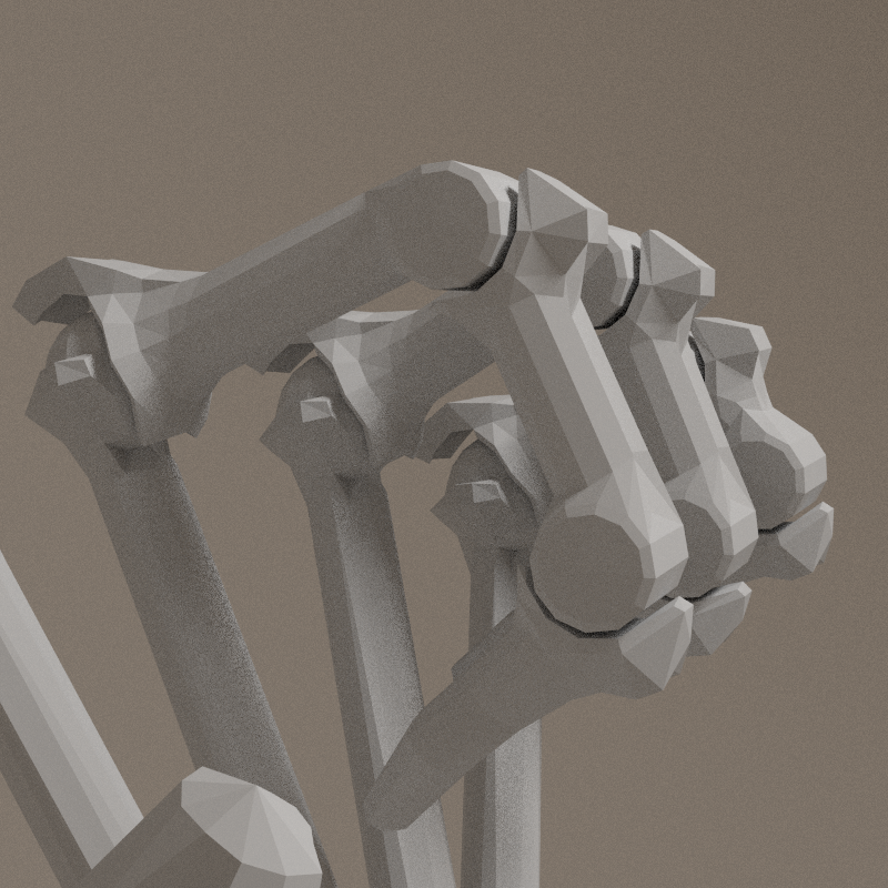
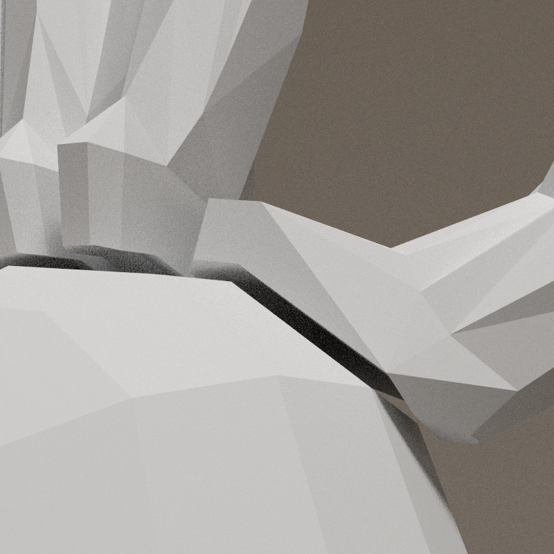
Complex articulation flushed out! Back to a sphere! The overall shape appears smoothly => it's the right shape. Stilll to do: re-orient fingers.
Not convinced...
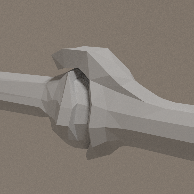
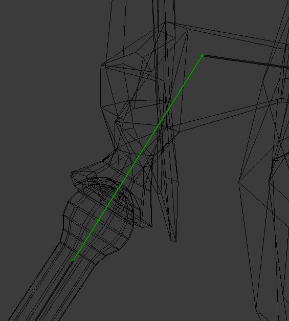
Wrist
The rigging of the hand from makehuman stops me to rethink a simple mechanical structure.


Adapt the rig: metacarpals are directly connected to the wrist sphere (see sketchbook )

It's been a hell to have the metacarpals correctly oriented: the adjustment of the bone's roll has to be precise to the 1/10° for the rotation on X axis to be aligned with the sphere's lattitude! I should have a look to the matrix of the bone and arrange that there.
Rule:
- X axis of the bone's orientation MUST be in the XZ plane ( hand's looking up ).

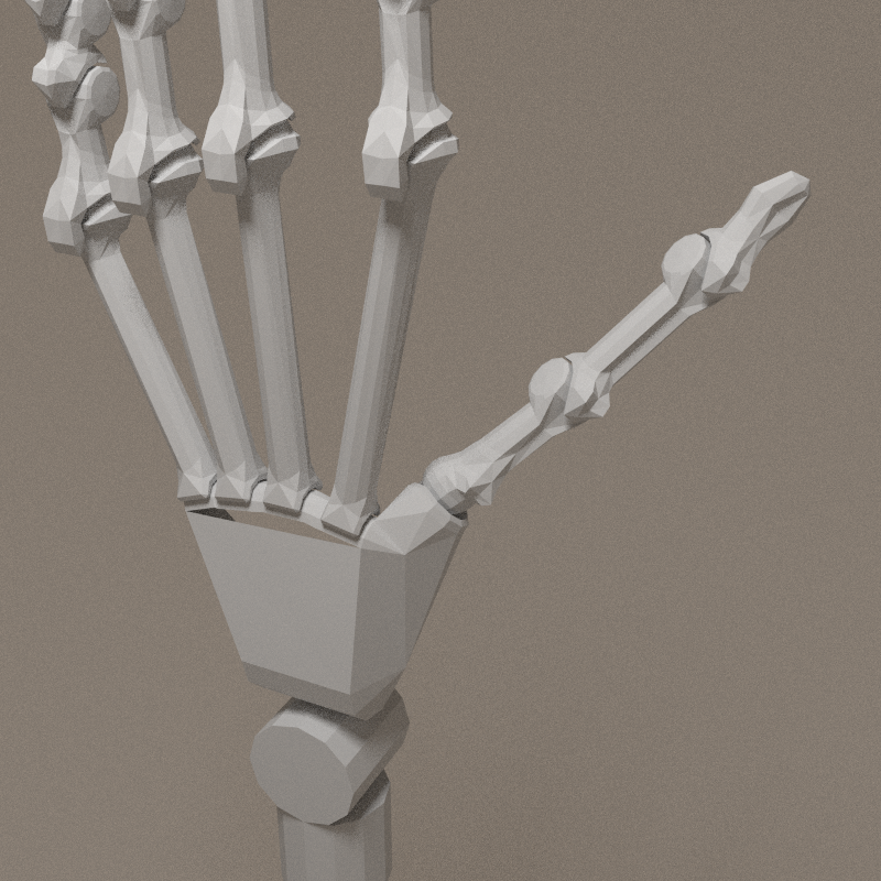
Pallets must be thinner -> there are centred on equator, if it goes towars the poles, the space between pallets becomes narrower. The rotation at this artication must be of a few degrees.

Thanks to sebastien noel, I spotted the roll control functionalities in blender - see image above - meaning i can rebuild the metacarpians. Rotation axis are correct. The space between each pallet has been increased: more space = more angle.

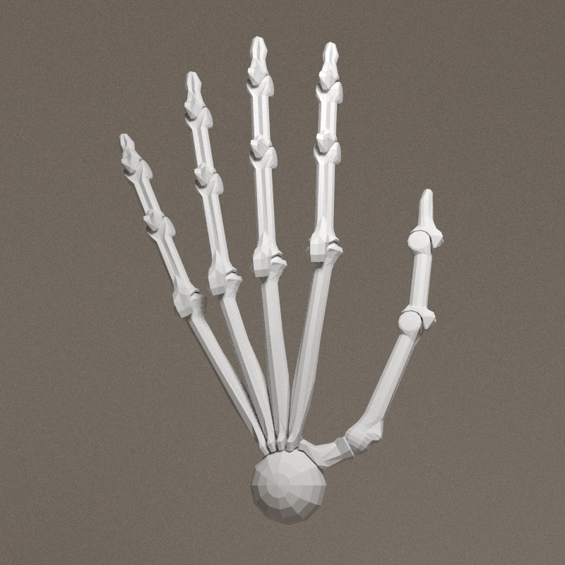
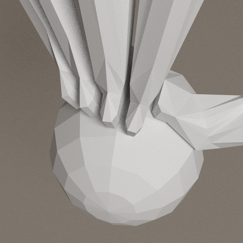


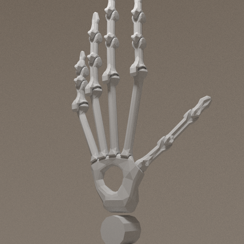
With a little help of my friends, the hand is now complete and functional. The nice trick to close edge loops is to use Bridge edge loops. It's tricky to master:
- pick a vertice on the first loop
- hold SHIFT + ALT
- pick another vertice on the first loop
- hold SHIFT
- pick a vertice on the second loop
- hold SHIFT + ALT
- pick another vertice on the second loop
The 2 loops are now selected and can be bridged!
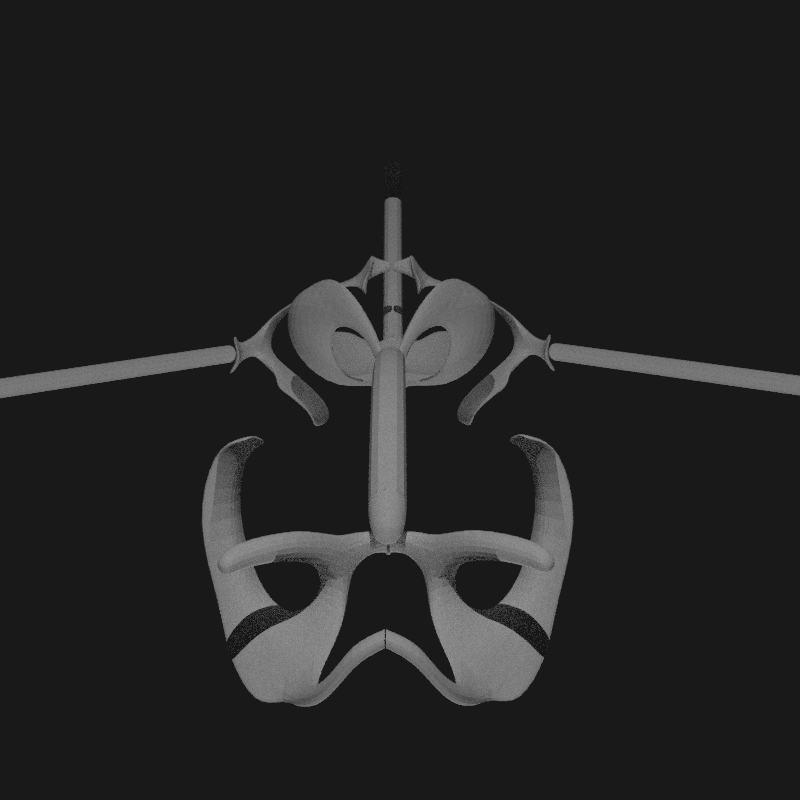
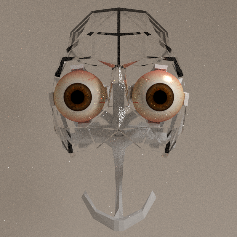
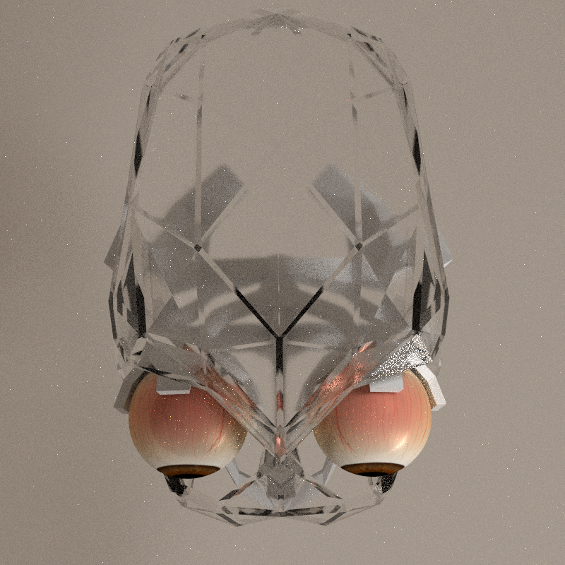
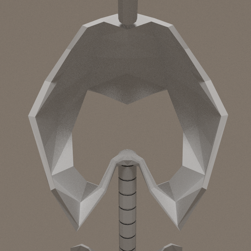
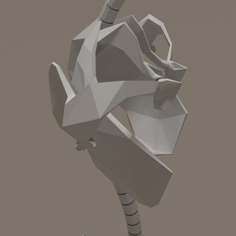
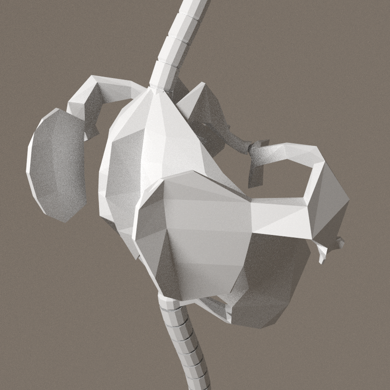
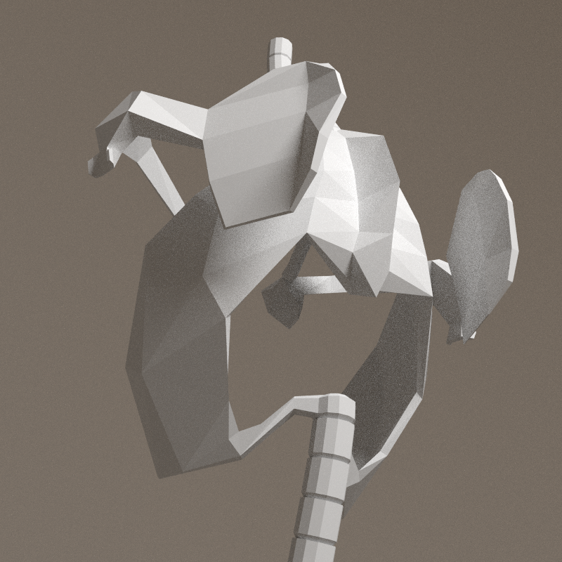
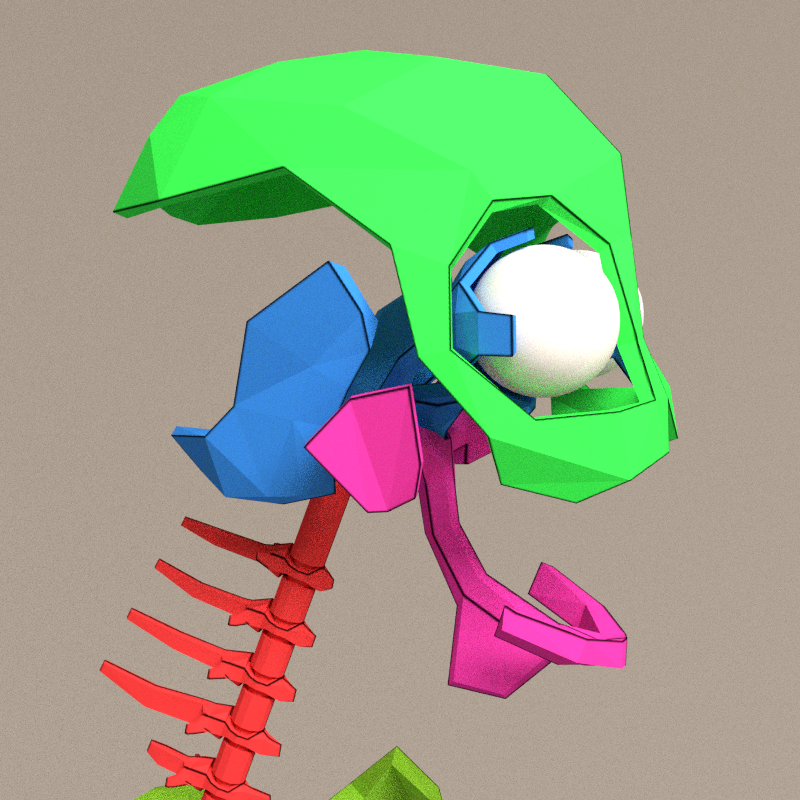
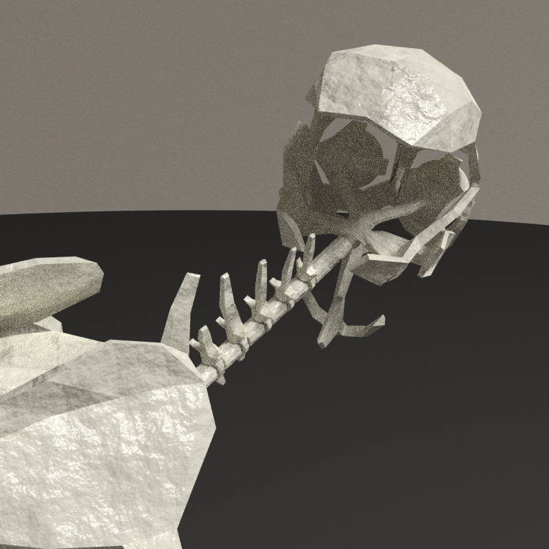
Skull
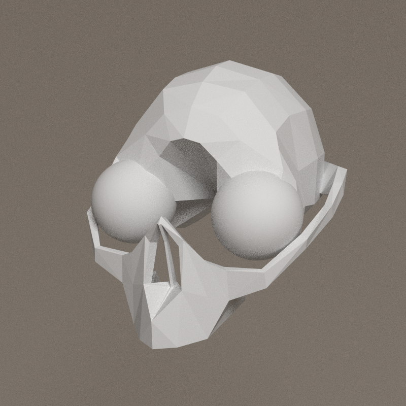
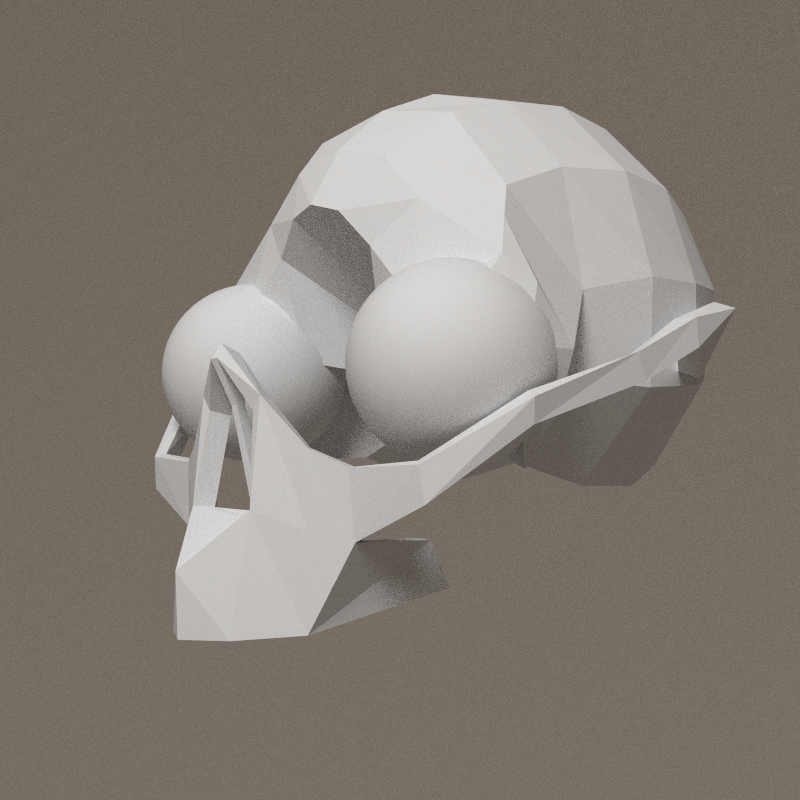
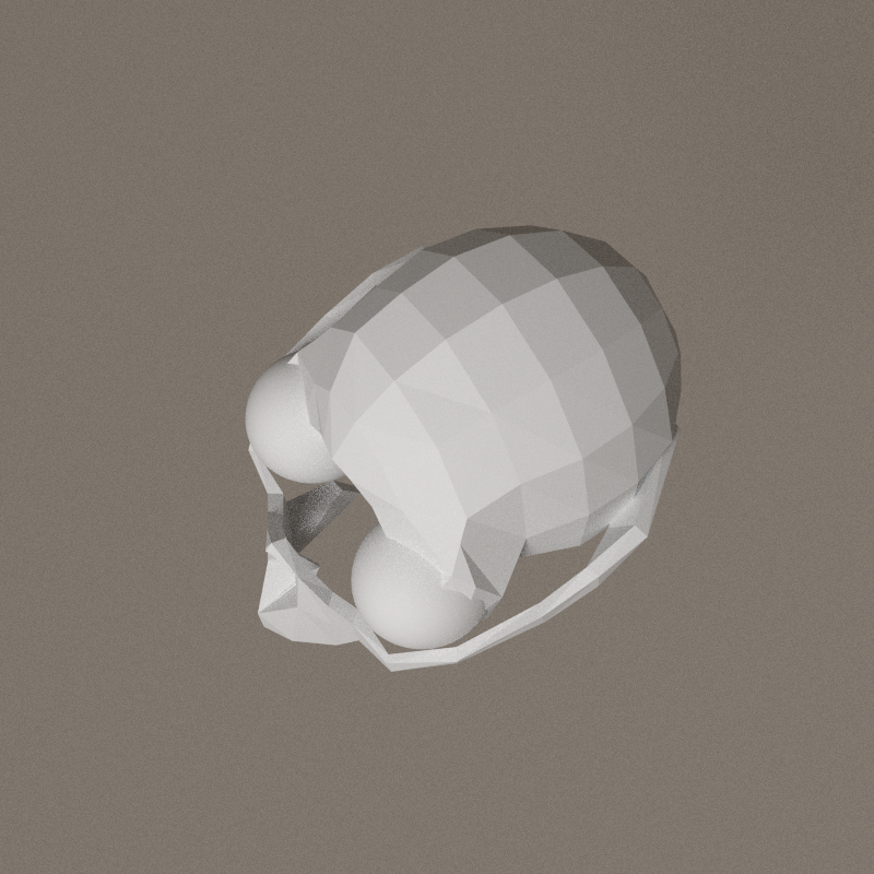

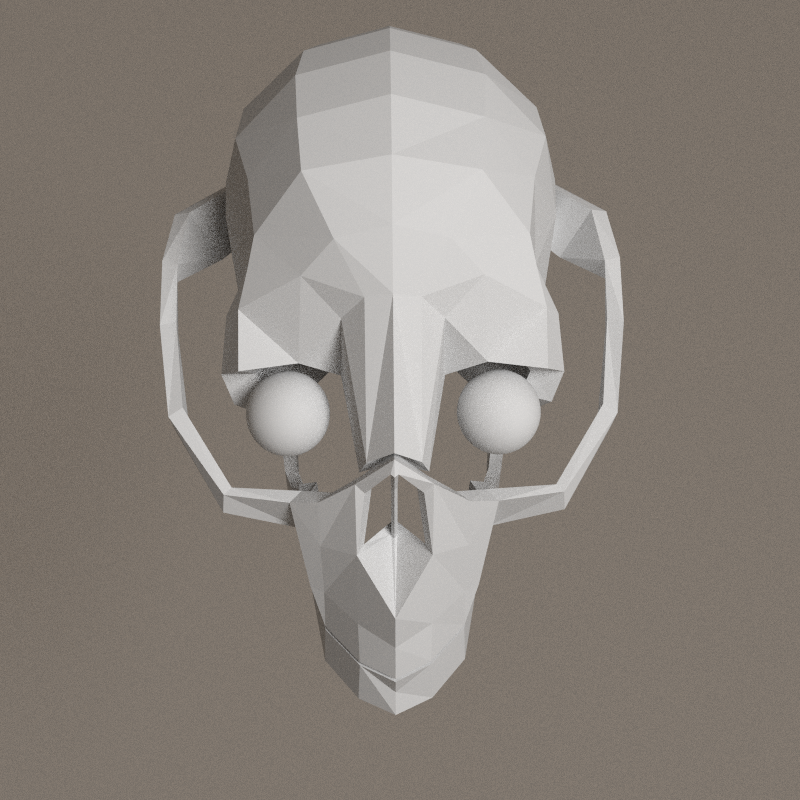
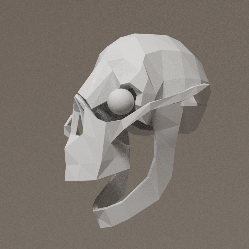
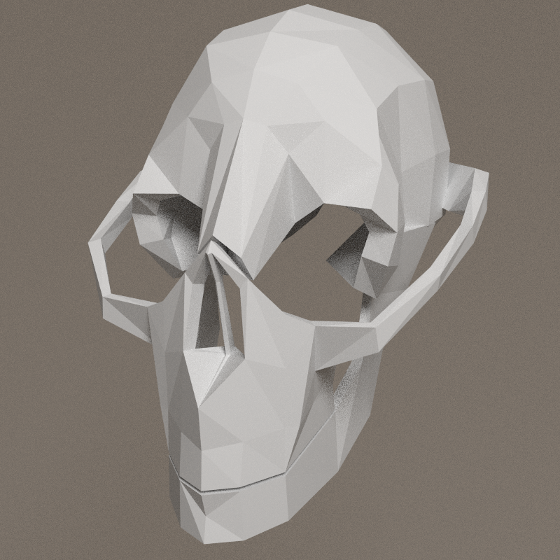
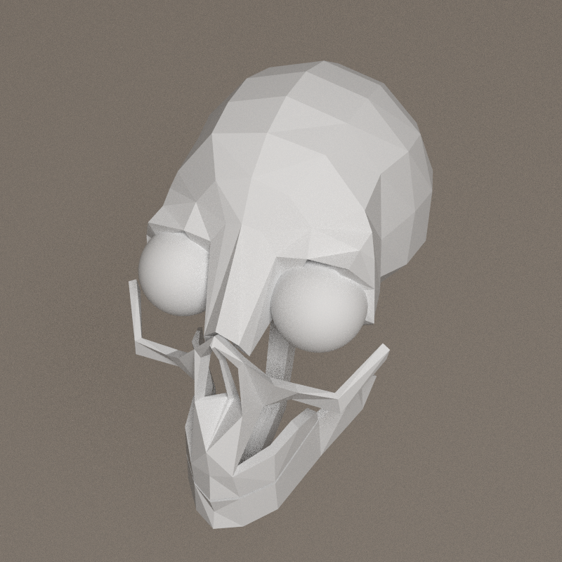


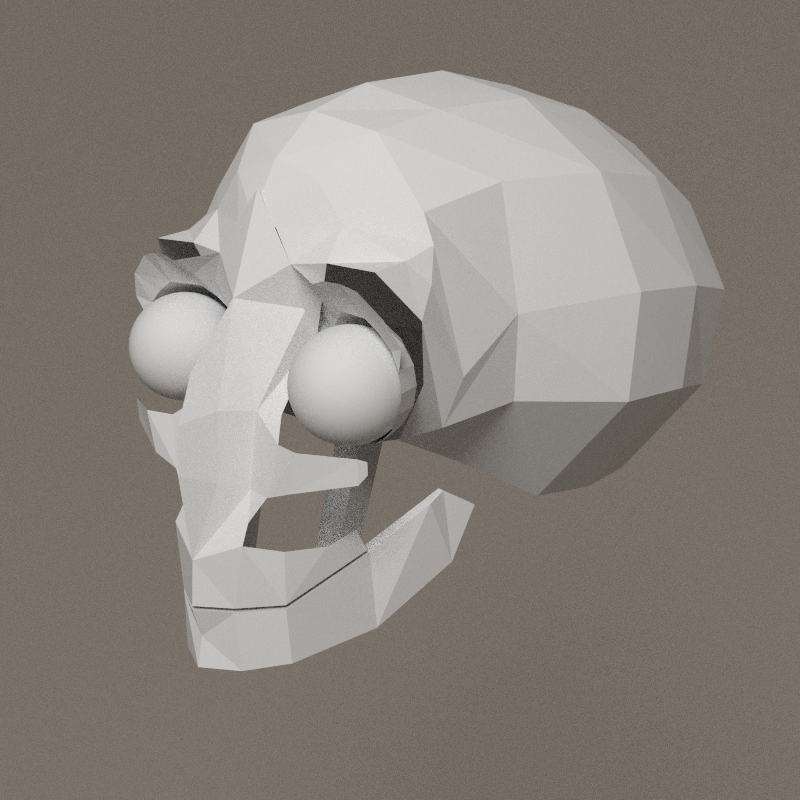
It's just a big mess. No idea if i'm making a human skull, a bone face or a machine. Attempts above are disappointing and not a blend of several ideas.
The shapes once again miss their function:
- Upper part of the face is there to hold the eyes
- Lower part gives the jaw its shape
- Back of the skull is only there for the shape
- Sides holds the hear
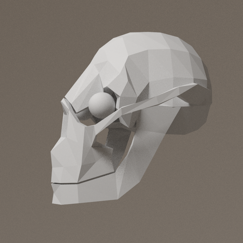
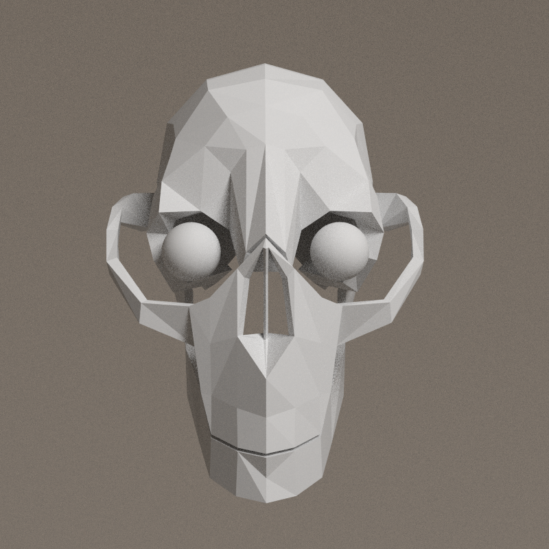
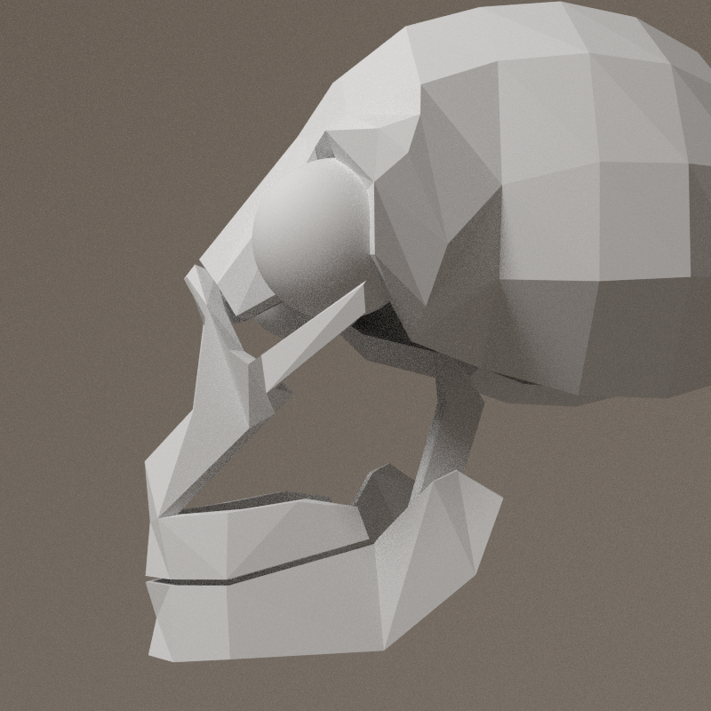
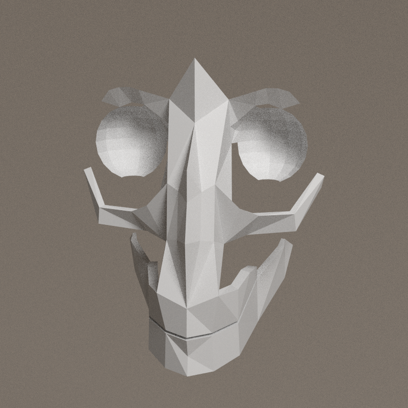
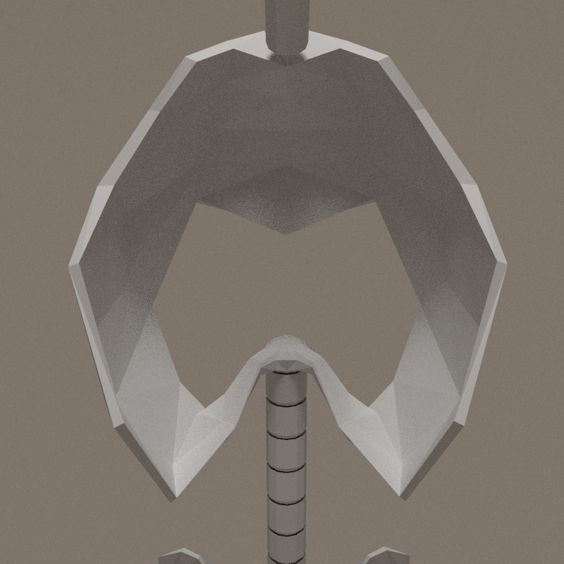
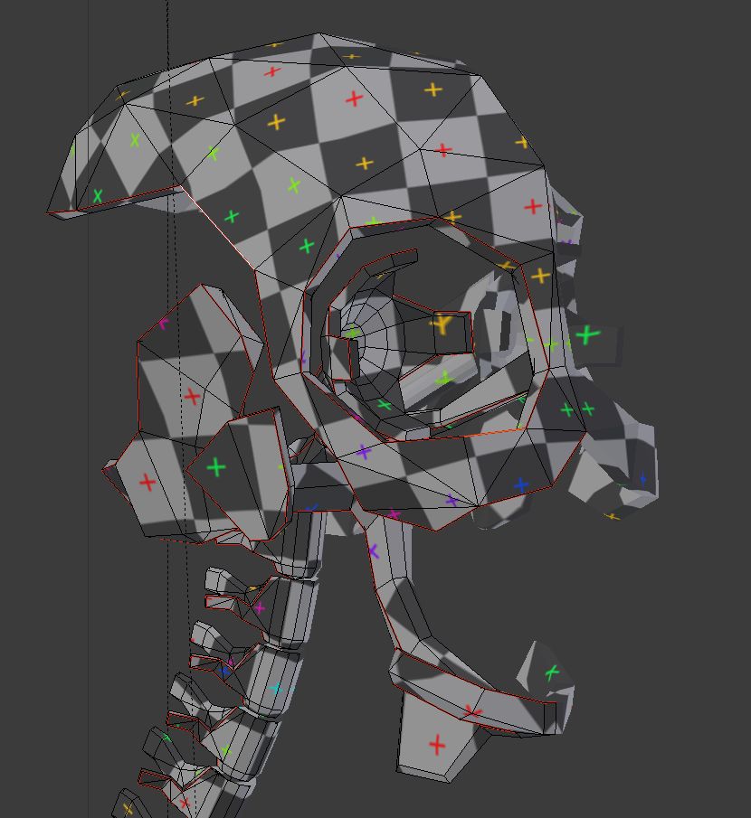
New workspace, with new resources, resuming all the aspects to find in the skull.

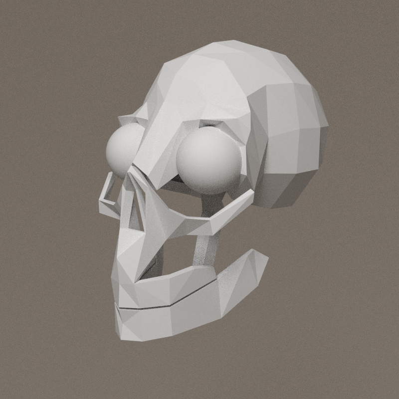
And, because works starts from a good approach, results show up!
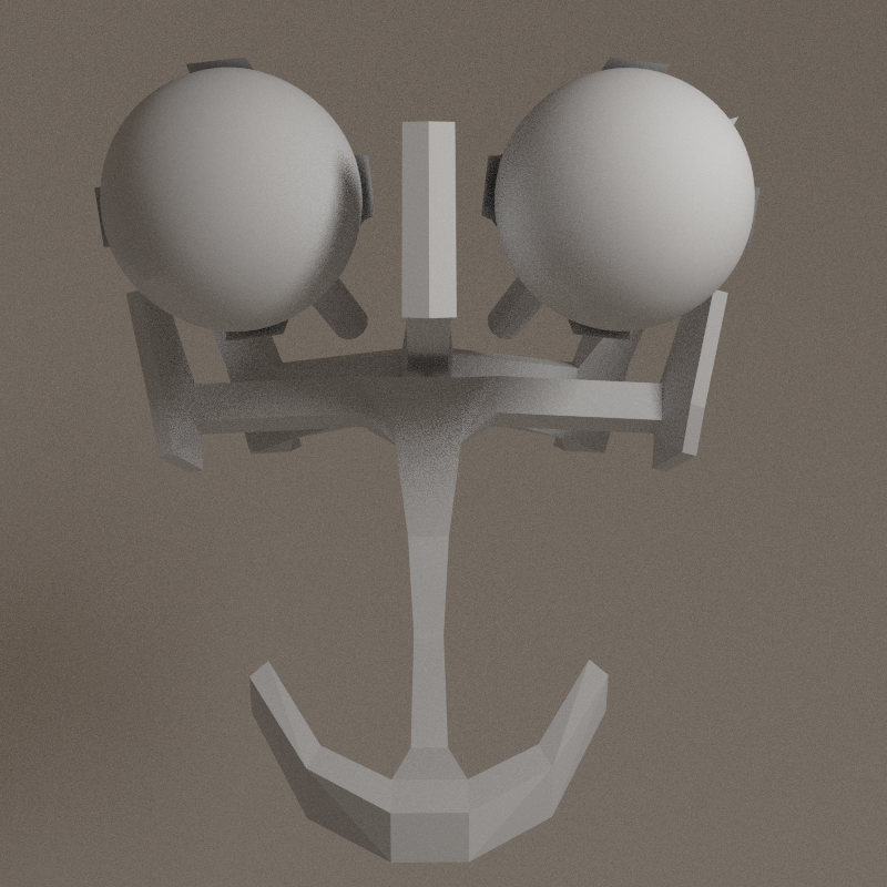


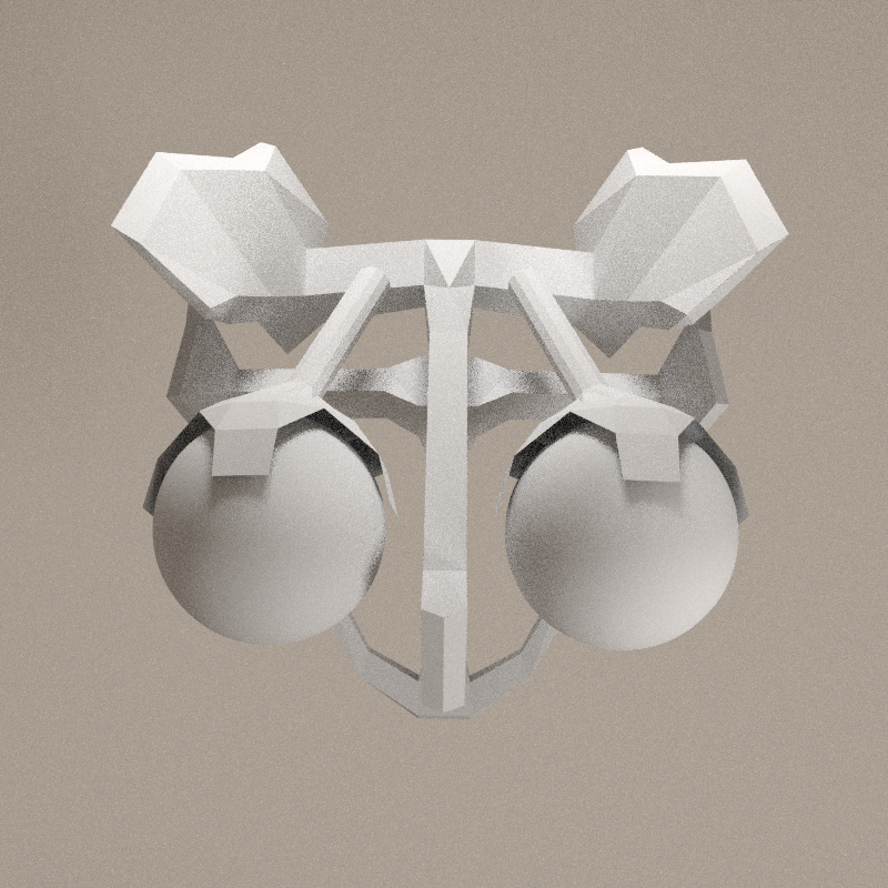
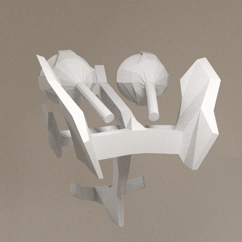
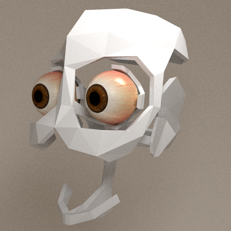
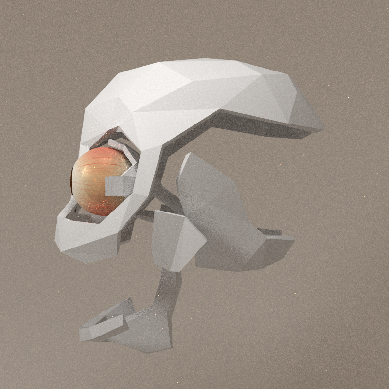
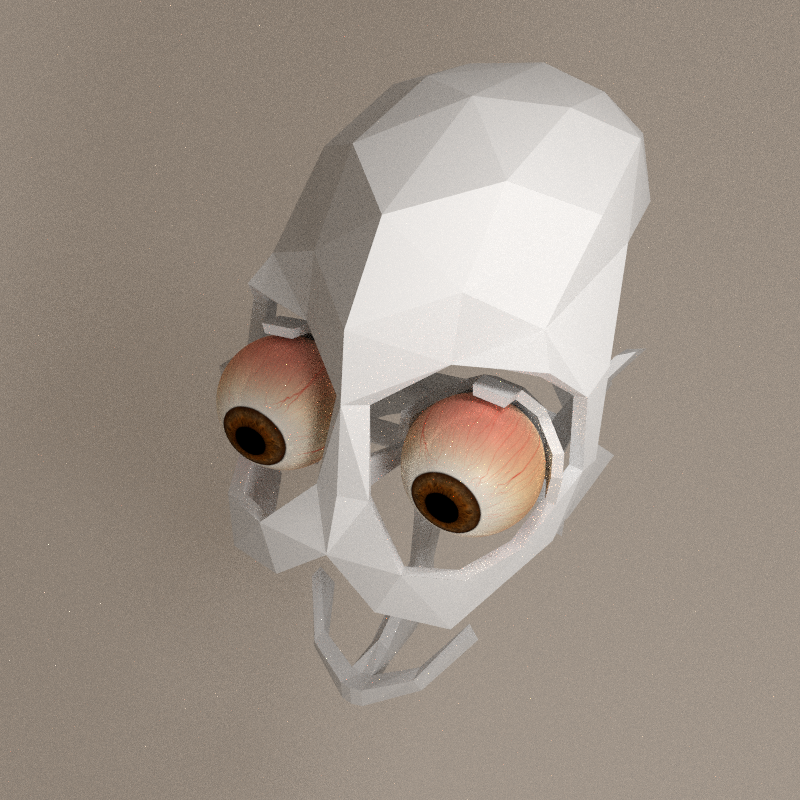
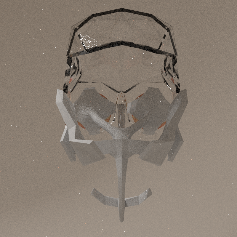
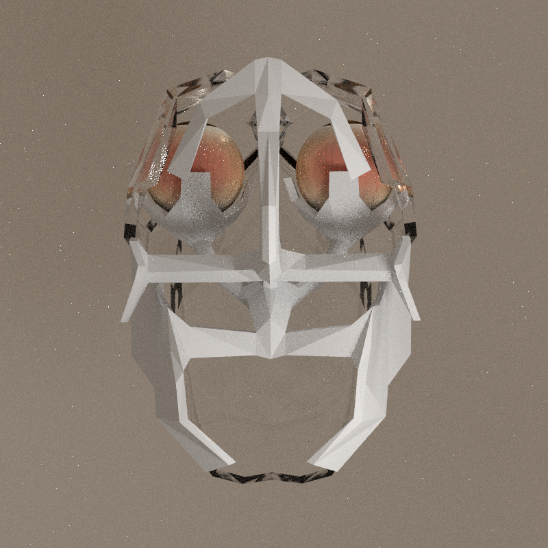
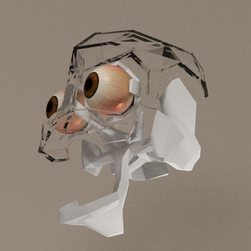
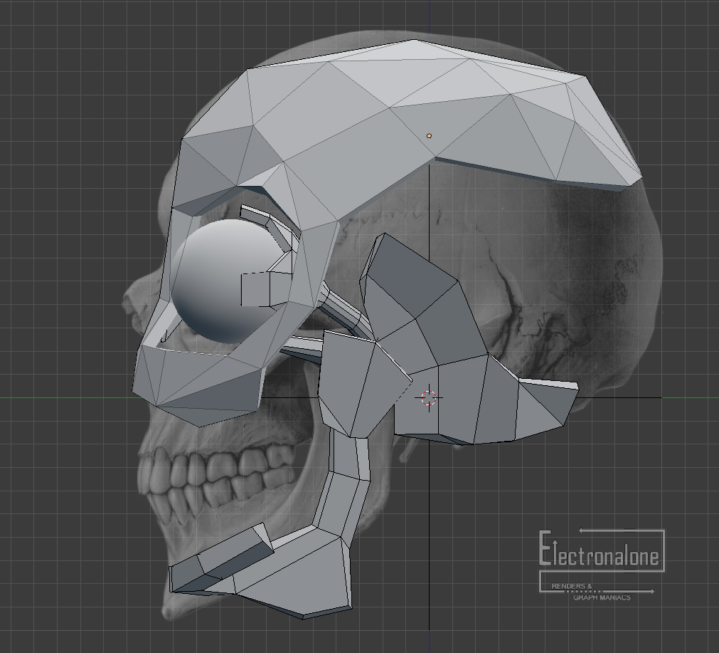
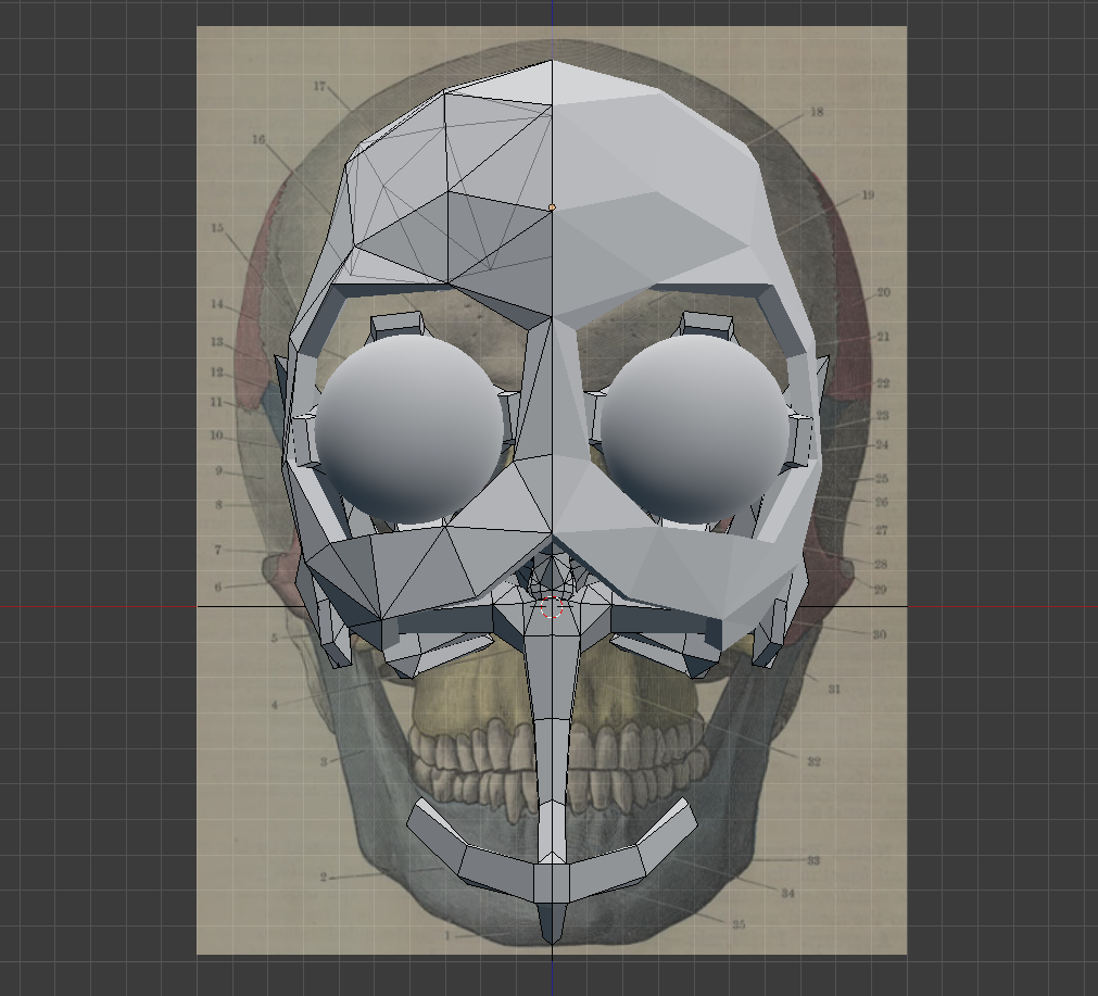
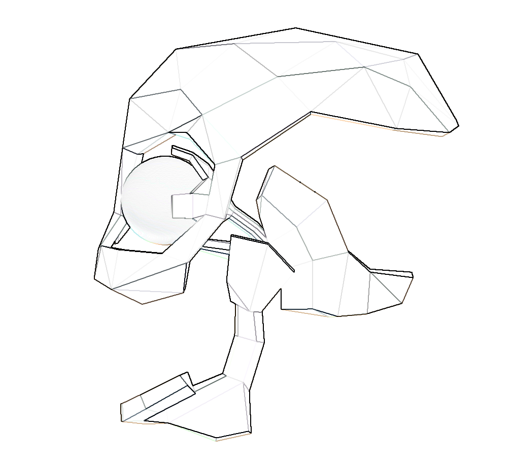
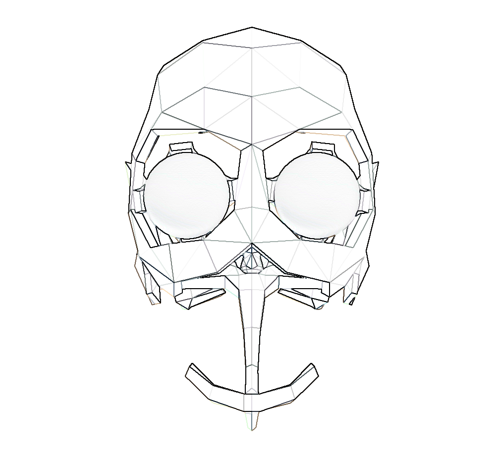
The structure of the skull is given by its mechanics, and not by the overall shape. The skull of a human is composed of a lot of separated bones. This model reflect much more the anatomy, in a way.

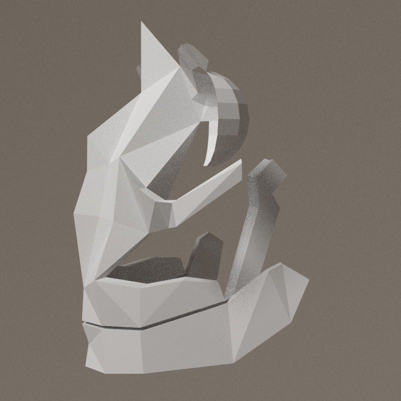
Jaw axis:
- X: -20° > 40°
- Y: -9.5° > 9.5°
- Z: -12.5 > 12.5°


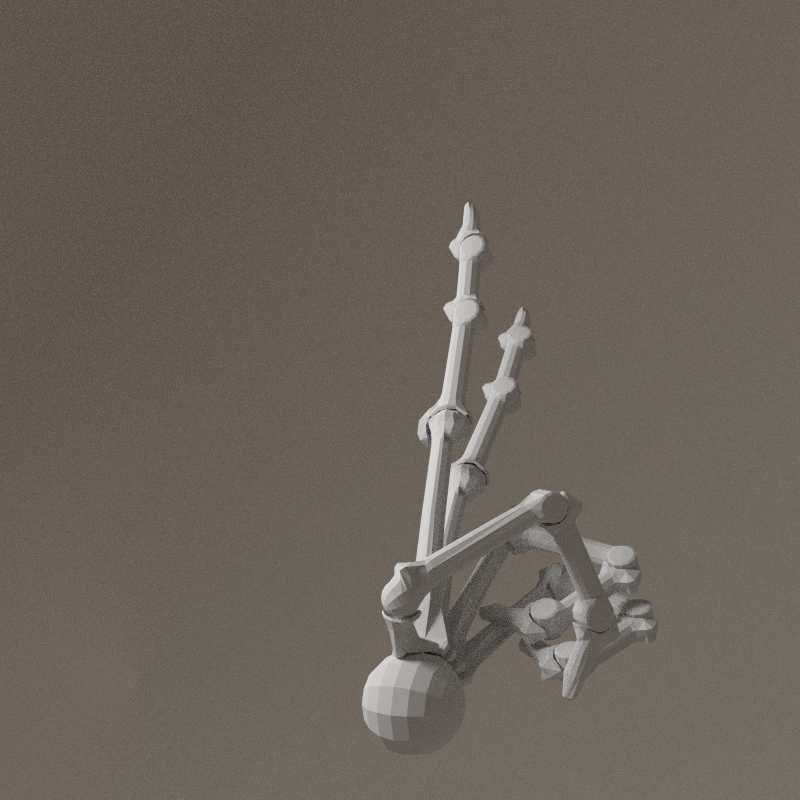
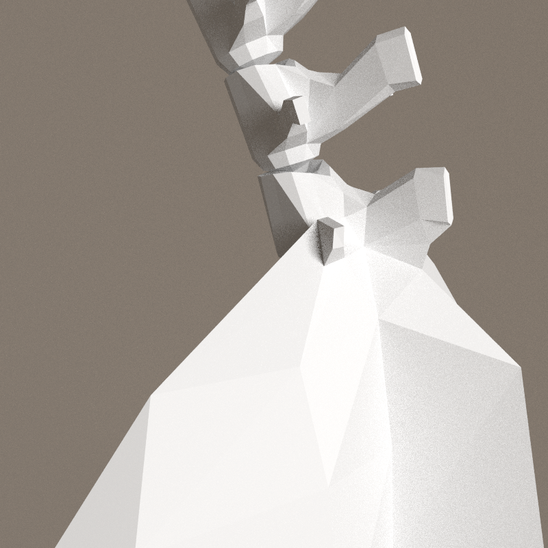
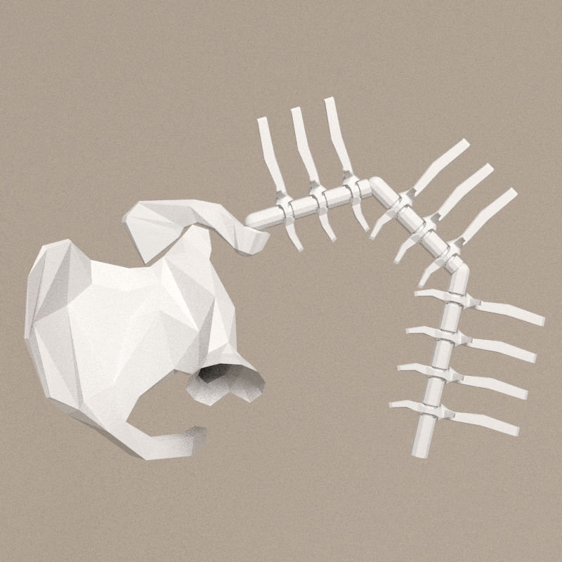
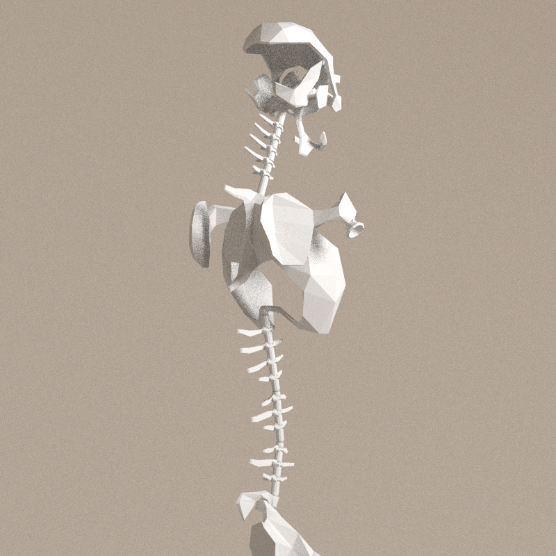
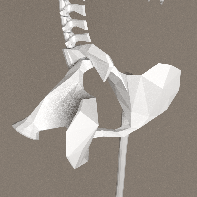
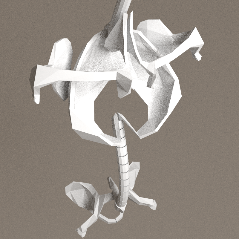
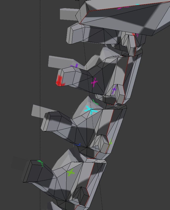
Spine
Buiding the spine.


Unskinnable
Stupid error of conception of the spine: that's the only part who is not following the general logic. Therefore, at the skinning phase, a huge problem occurs. Back to modelling...
- Flexion/extension and adduction/abduction[2] ( bending forward or on the side ) can't be spread accross the vertebras. All vertebras of a spine's segment must follow the segment.
- Rotation[2] ( vertical axis ) can be spread accross vertebras. If the lumber 1 segment have a rotation around its direction - Z axis in the armature - this rotation can be applied gradually among the vertebras.
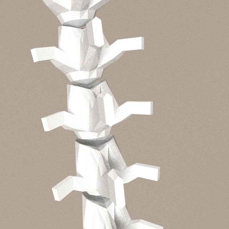
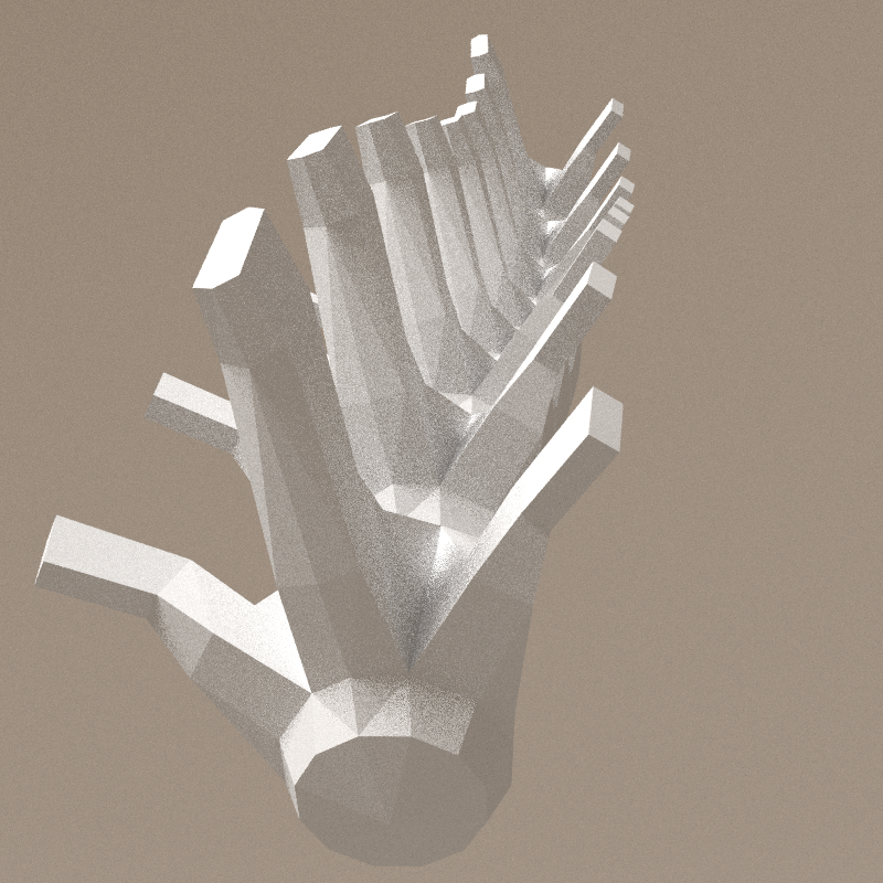
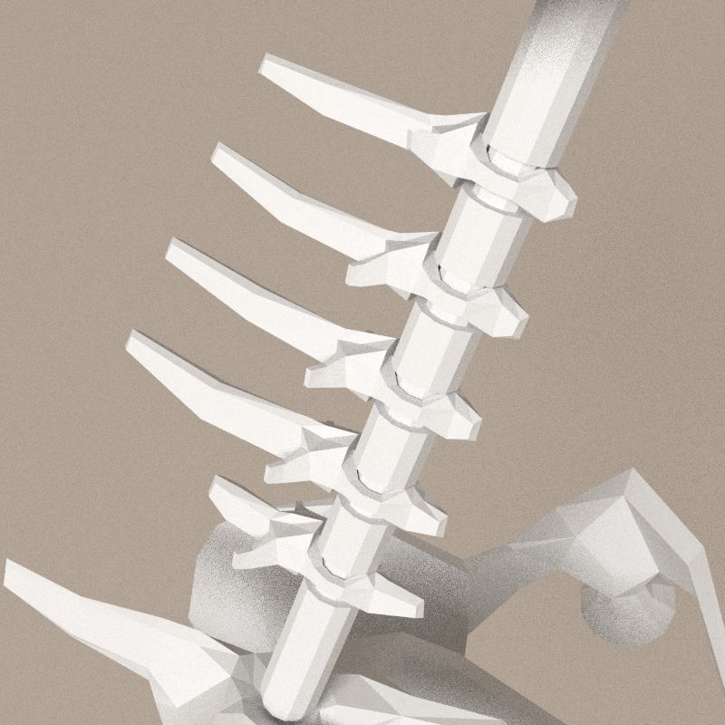
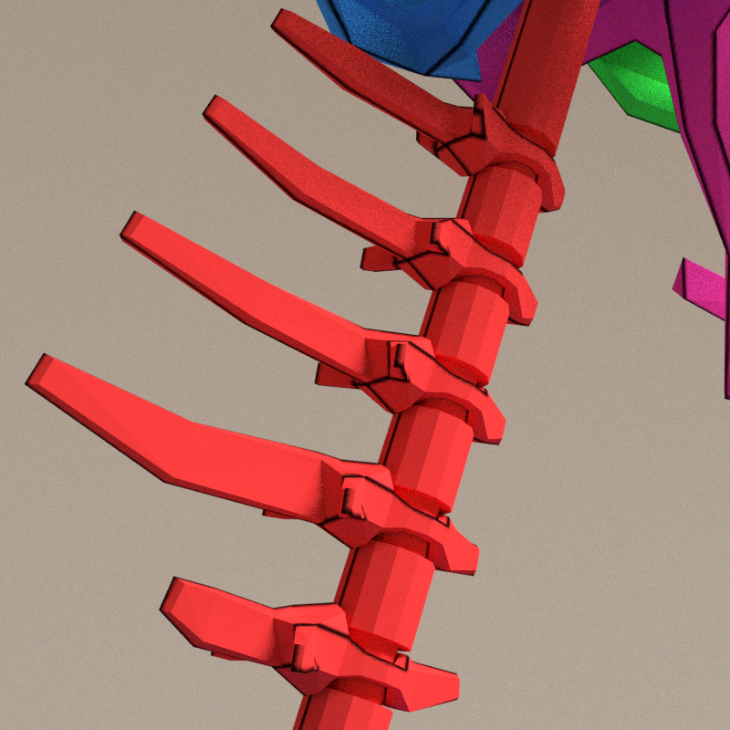
Each segment of the spine becomes a kind of stick with processes[3] rotating around it. A little sketch will be clearer.

The sketch being quite clear, the modelling was fast.
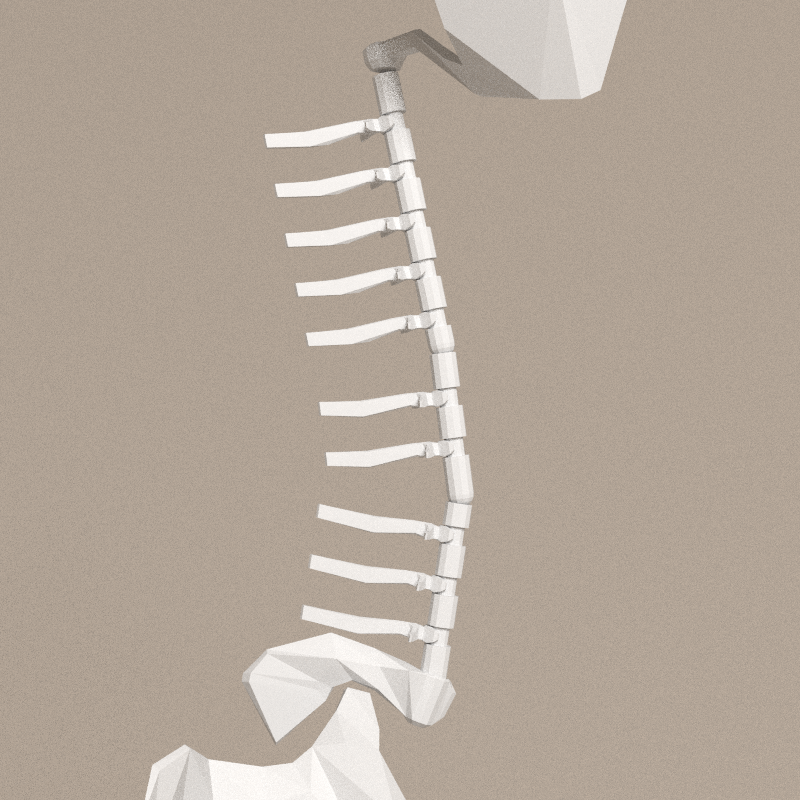
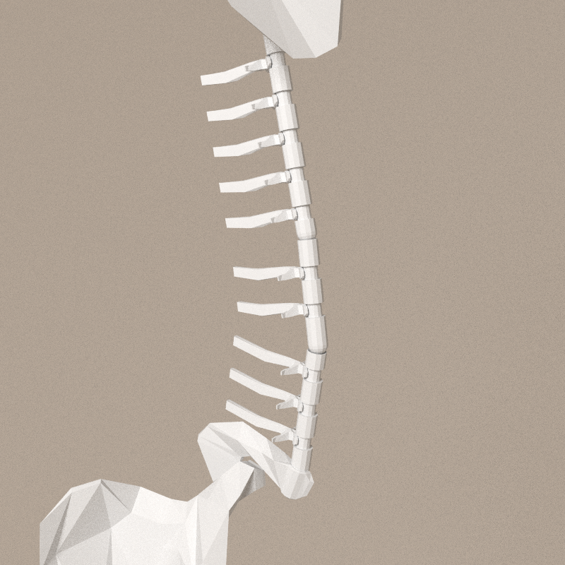


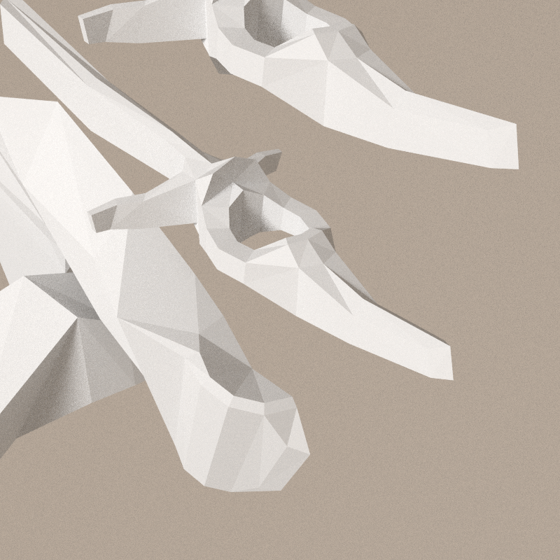
The vertebras are rotating in only one axis, parallel to the spine bone. This spine is a cylindrical bone, with a convex and a concave endings, with gutters to keep the vertebras at the right location. In the first version, the vertebras had human processes, pointing to the back only. I lacked anchors at the front of the spine to ensure the upright position of the body. That's why I added one process pointing forward. This solves also the connection between the vertebra and the spine: no need to image a complex tendons system to hold the vertebra. The vertebra becomes inseparable of the spine.
The curve of the back processes have to be adapted once the structure is ok. Currently, the model uses modifiers:
- spine:
- boolean - difference with gutters
- mirror
- gutters ( invisible in the renders )
- solidify - the gutter is just a part of a cylinder
- array
- vertebras
- array
- mirror
For the spine, the order of the modifiers is important.
Human vertebra compared to tanuki vertebra.


Limits


- adaption of the coccyx - spine junction (tanuki-20160406.blend-001.png)
- testing maximum spine rotations: (tanuki-20160406.blend-002.png)
Even if i like the look of the vertebras, they restrain too much the rotation of the spines.
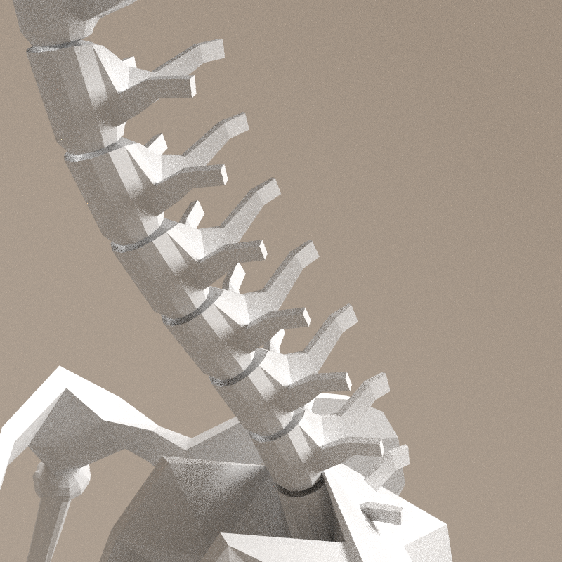
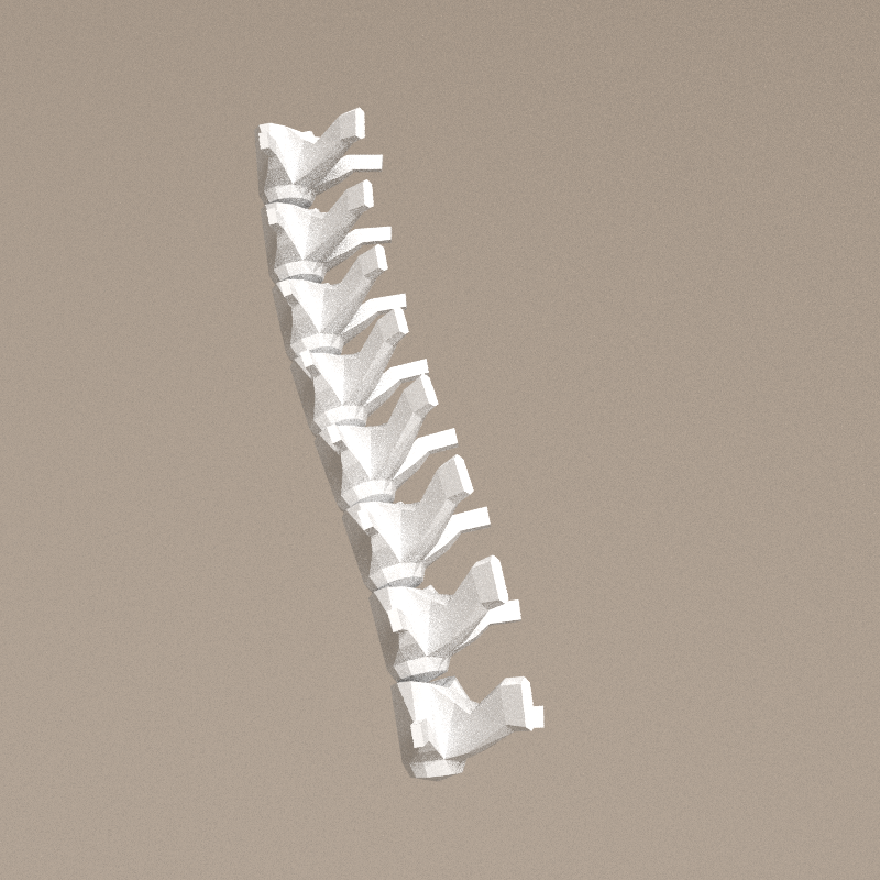
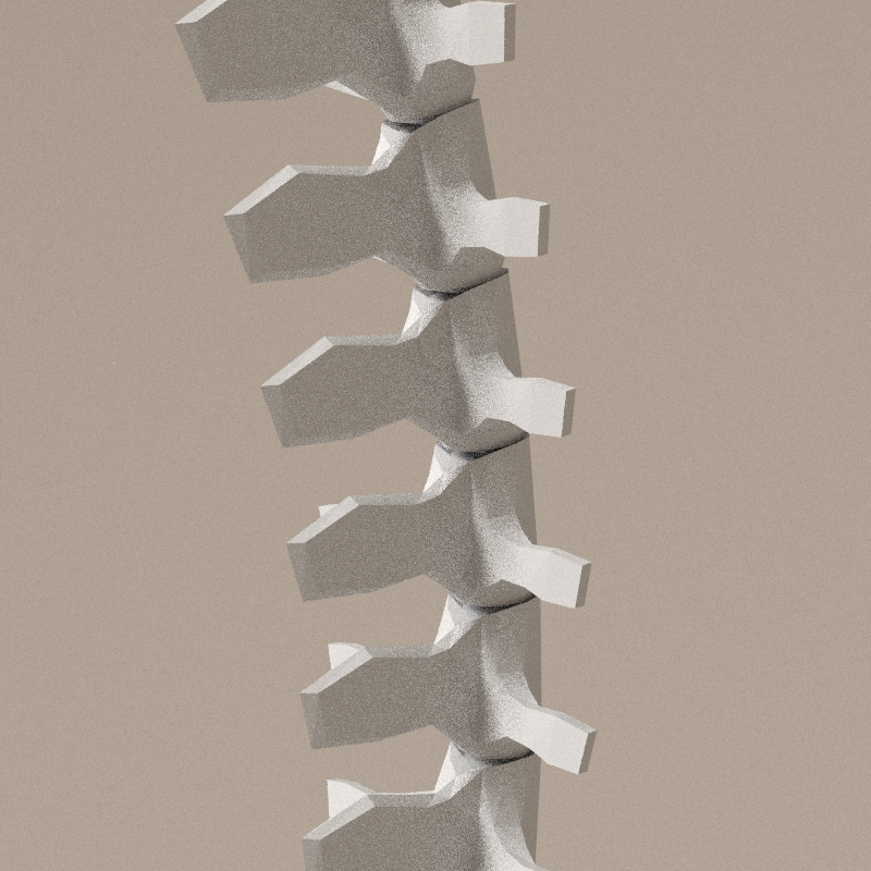
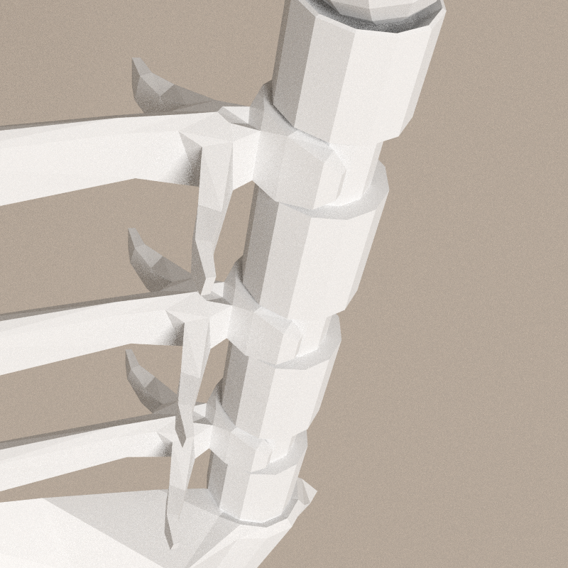
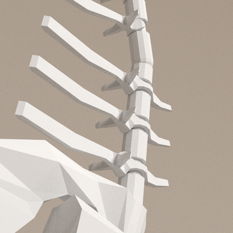
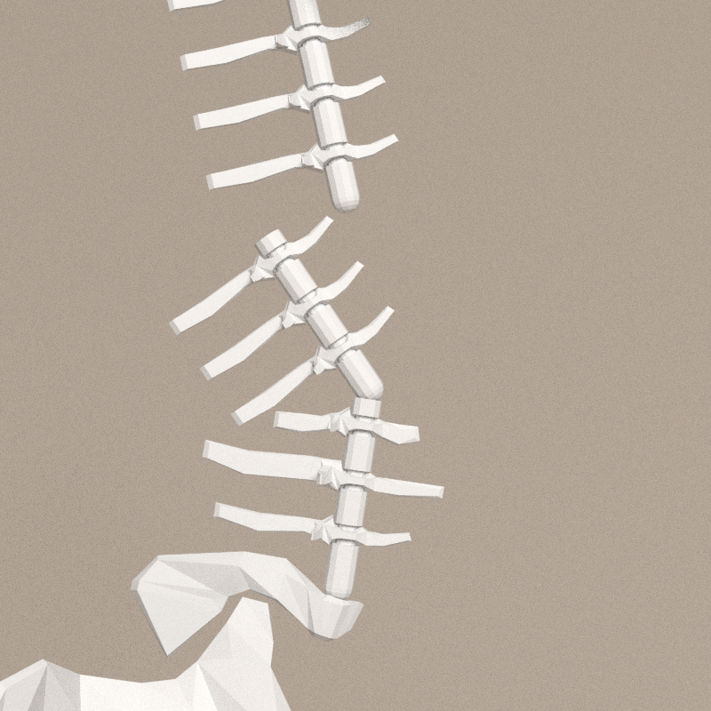
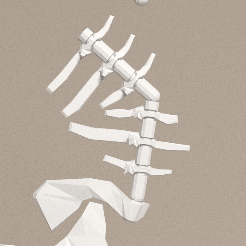
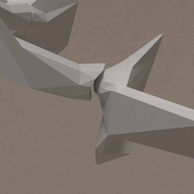
From image 005, adjustements of processes to allow large rotation of the spine. The rotation limits have been increased by 80%.

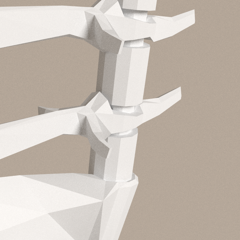
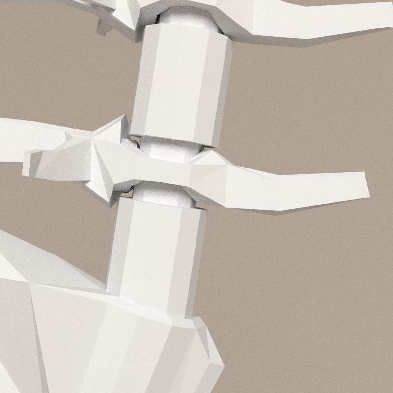
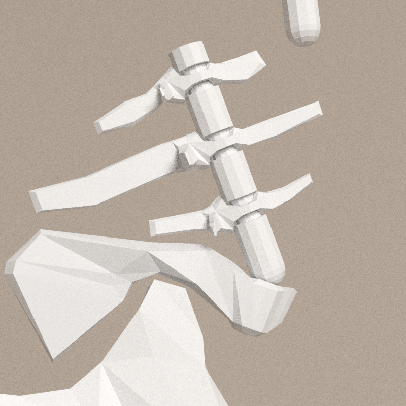
- The two first spine segments have the same overall shape, similar to a double-headed haxe. Bottom and top small processes allows the segemnt to bend very far. When bended, the ends of the processes are aligned.
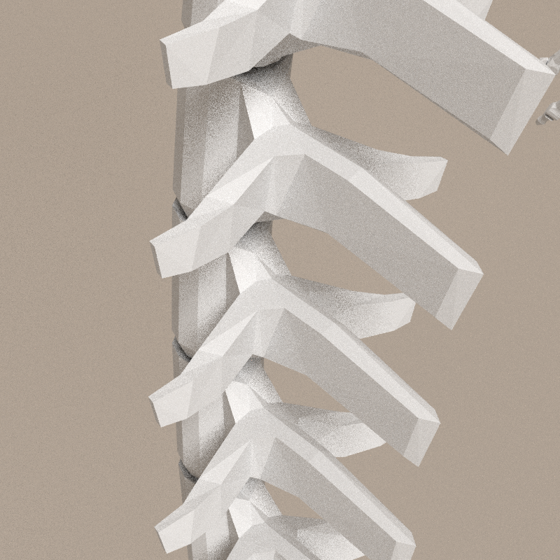
- The third segment, connecting to the thorax, is a bit different at the top. Processes are much larger for the muscles connections with the thorax. Front processes of the 2 last vertebras are shorter to allow rotations of the thorax.
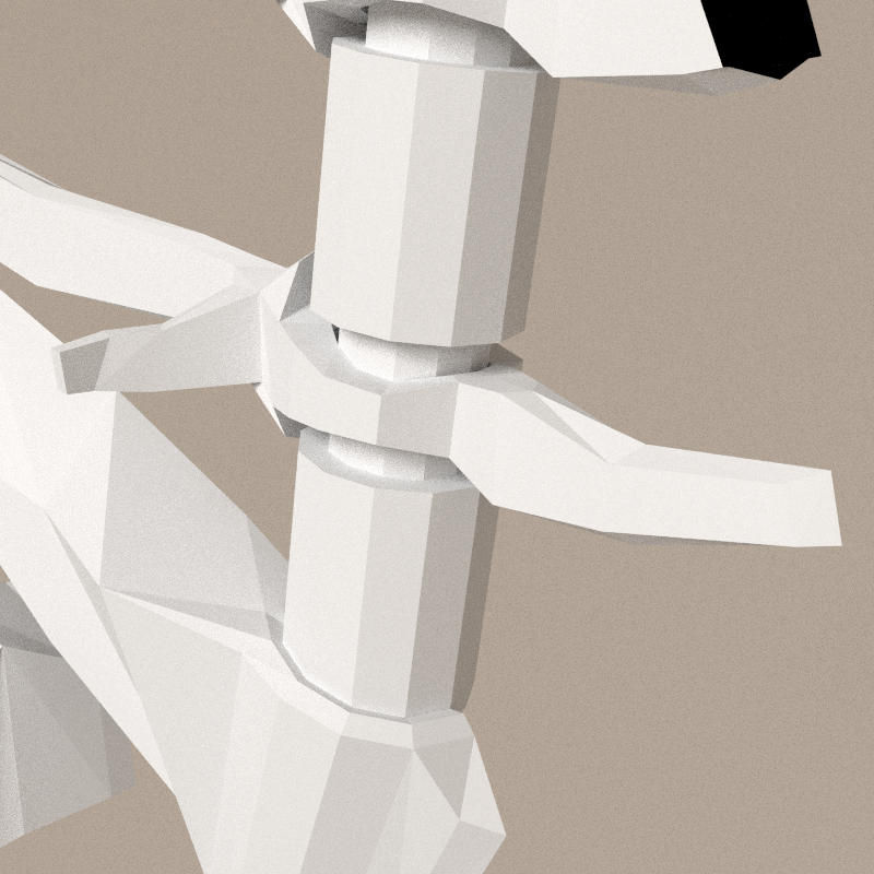
- The back spine of the thorax have been resumed to one process at the bottom and one at the top. Link with the neck's segment have to be done.
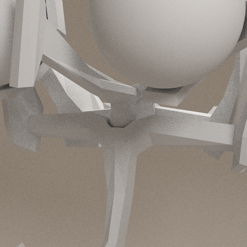
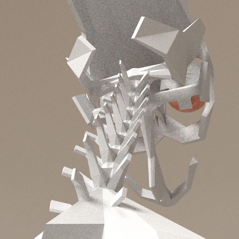
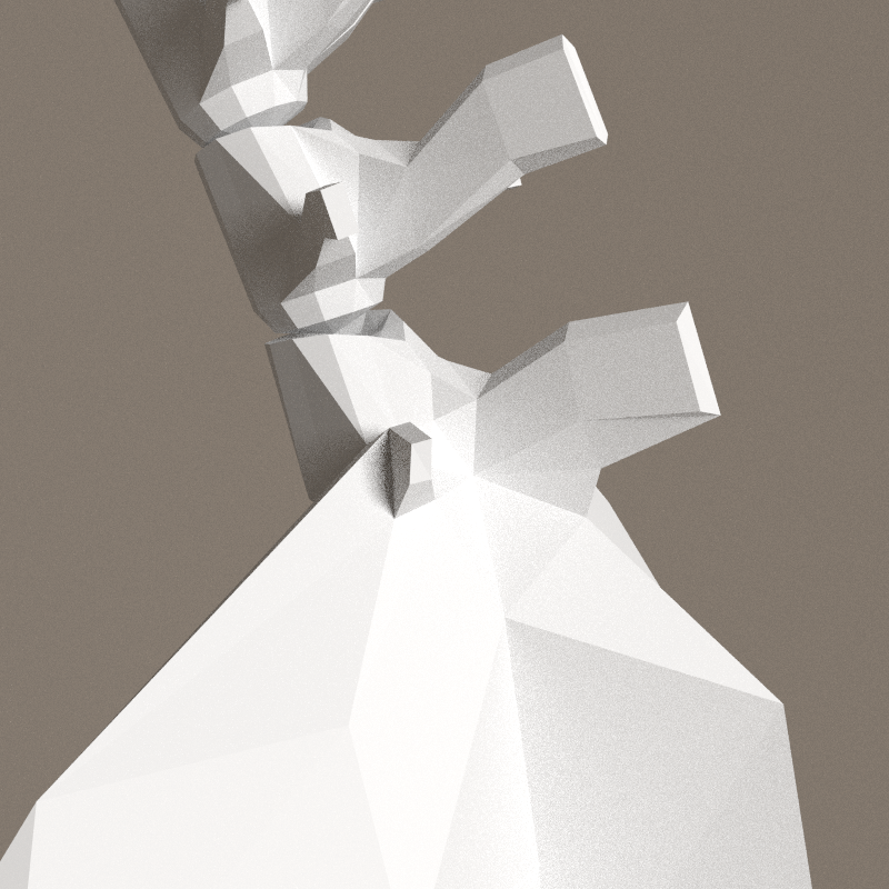
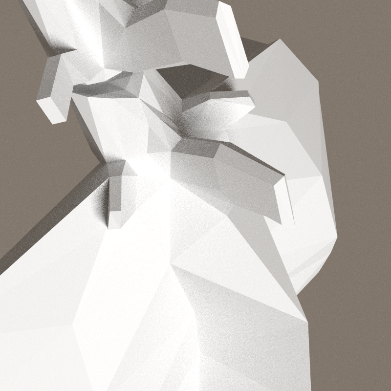
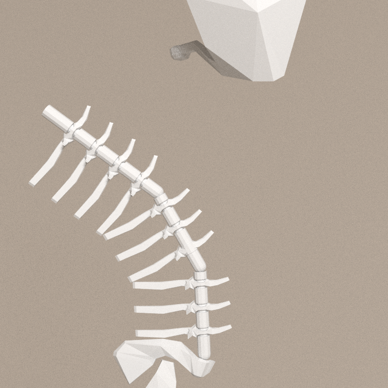
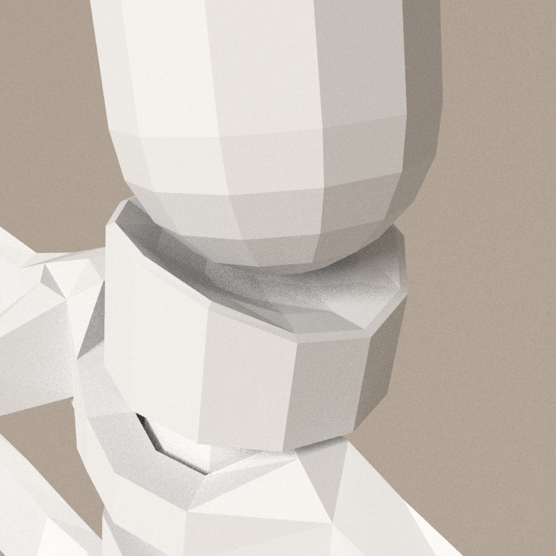
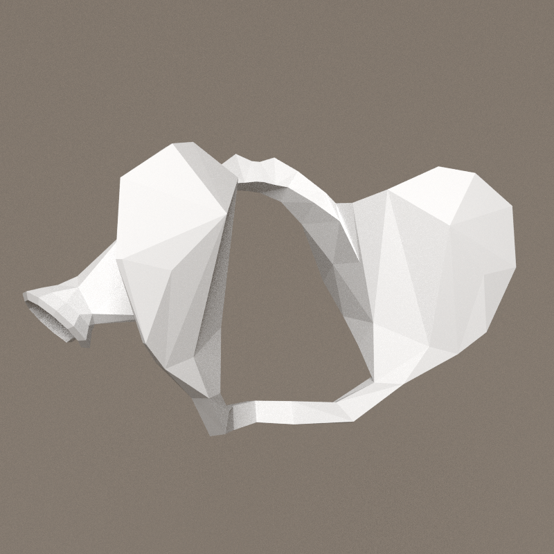
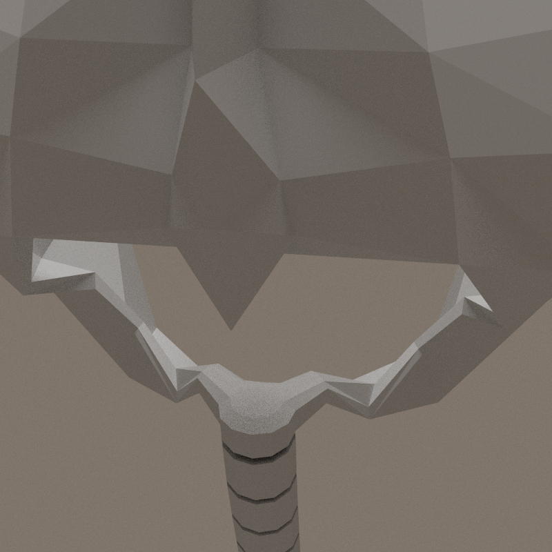
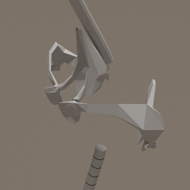
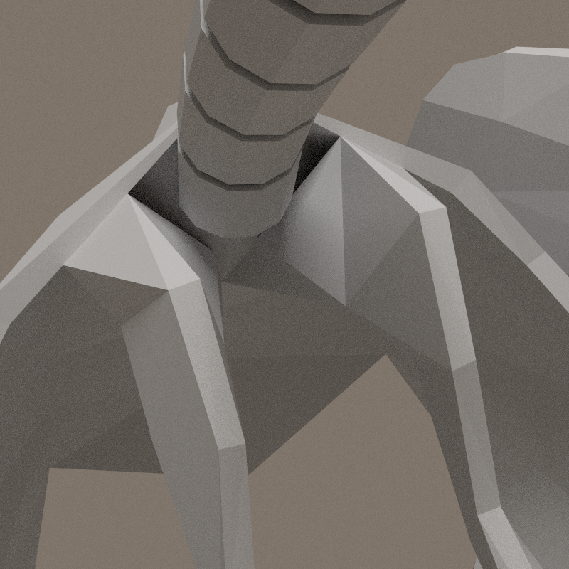
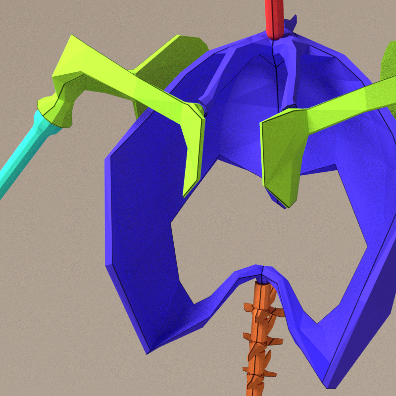
Thorax - neck
Connection with thorax is problematic: base of the neck must be free to rotate, not merge to the thorax.
The vertebra merged with thorax has to be freed. A space have to be made for the neck to bend. This means moving the basis of scapulas acnchors lower and rebuild this part.

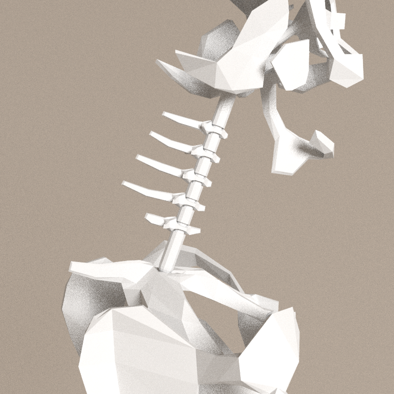
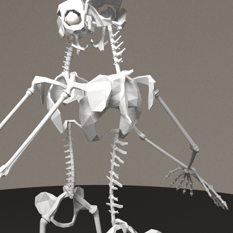
- Thorax rebuilt, basis of the neck is a large pan.
- First vertebra's back process is adapted to allow a large extension of the bone.
- Second veterbra's process is larger because it will be the main point of connection between the thorax and the neck.
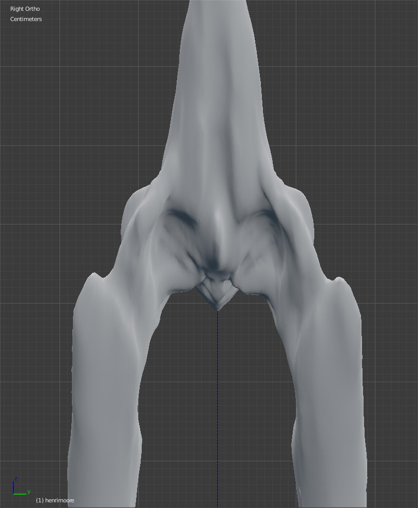
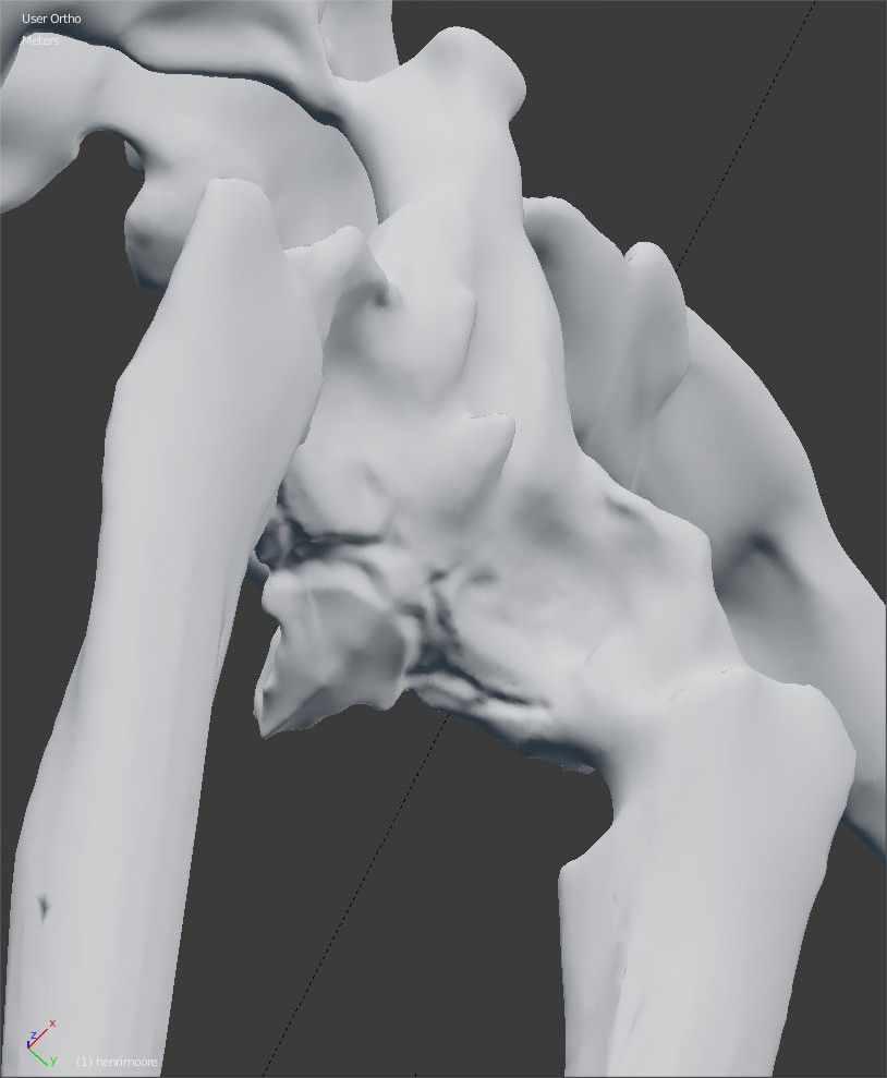
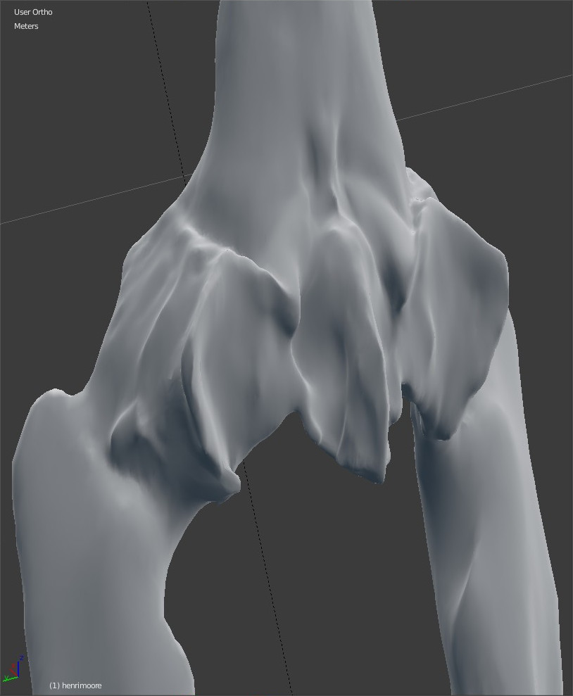
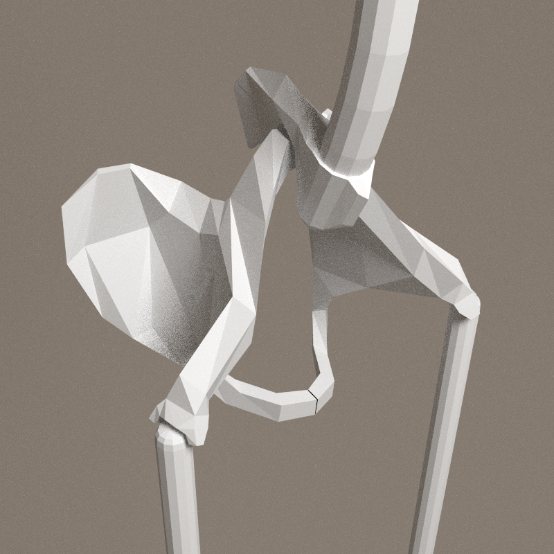
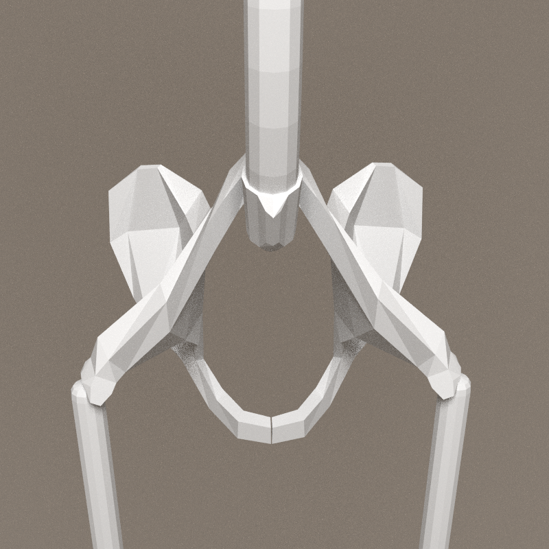
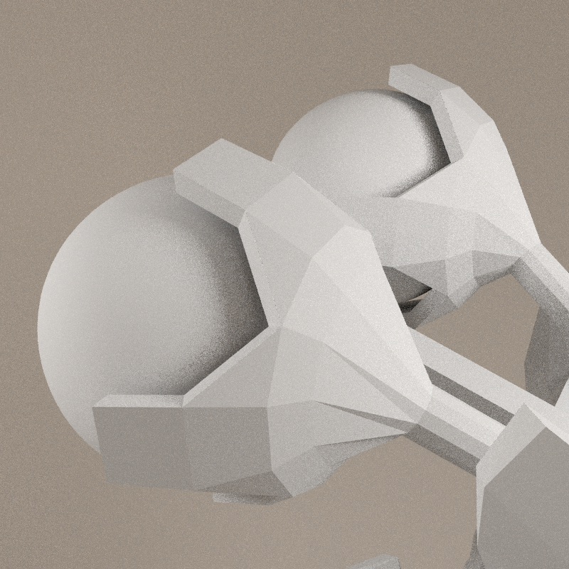
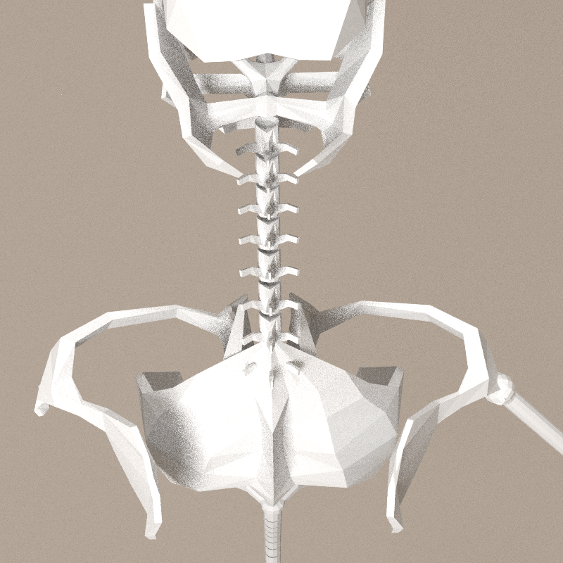
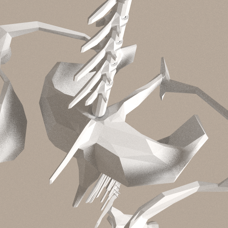
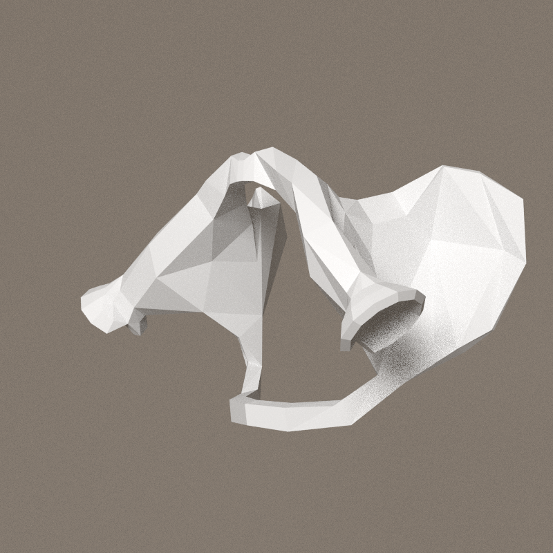
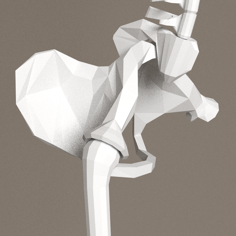
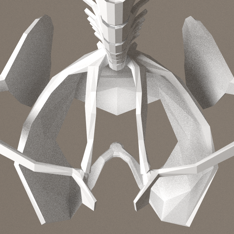
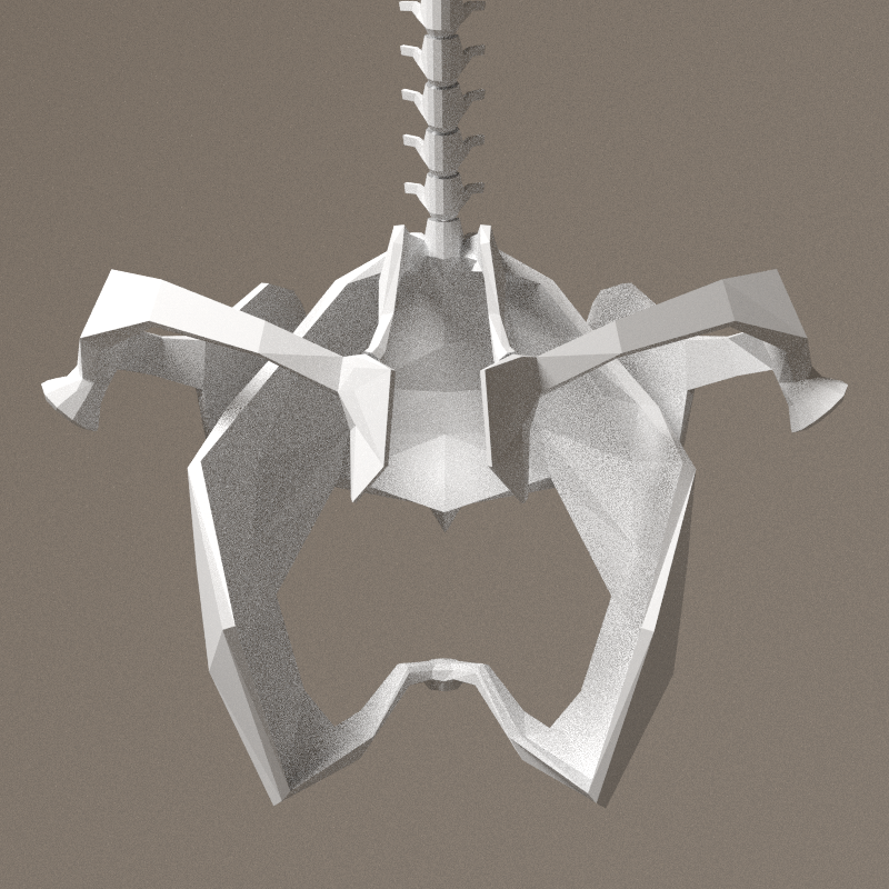
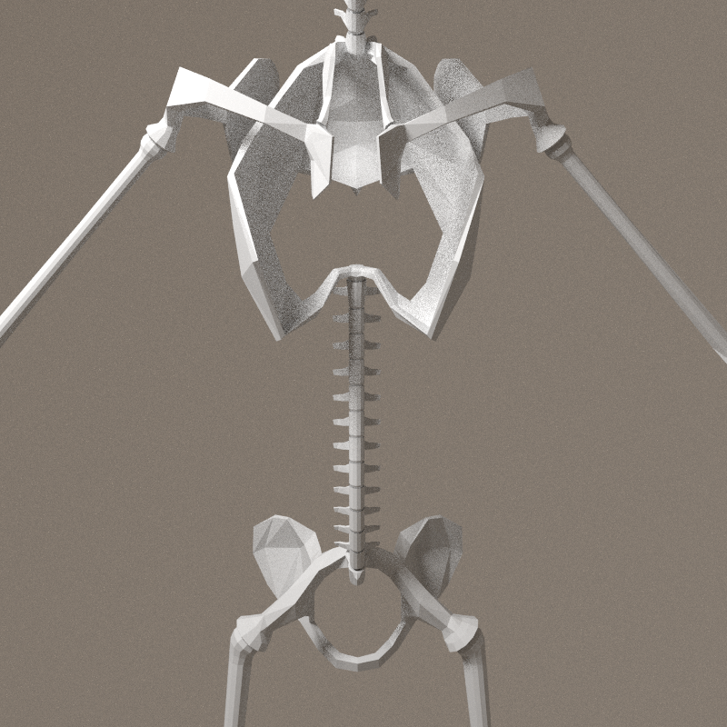
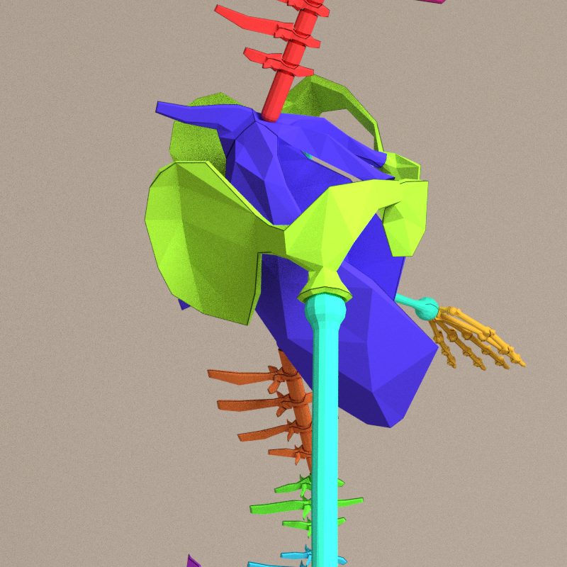
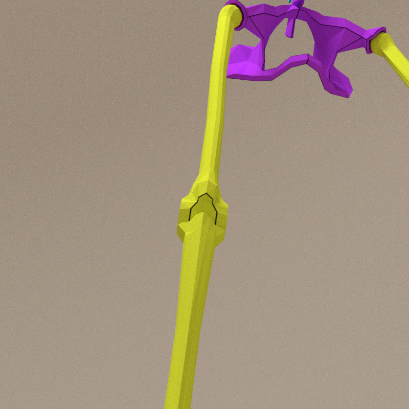
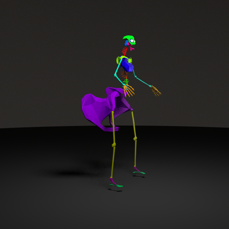
Hips
Finishing the hips, with connection to femur.
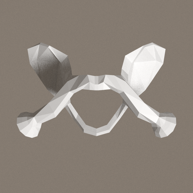

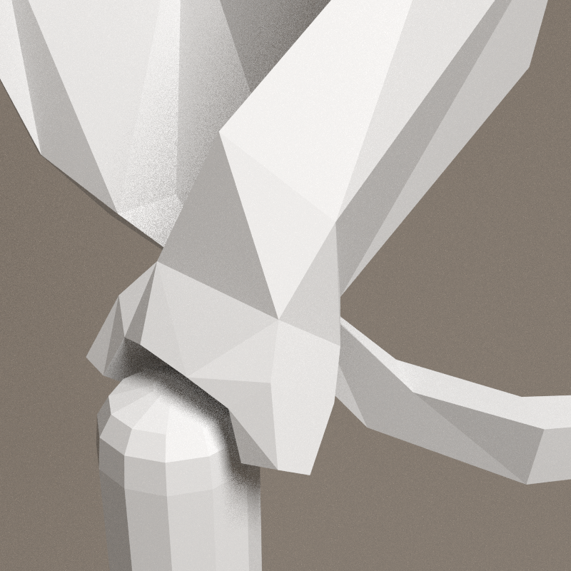
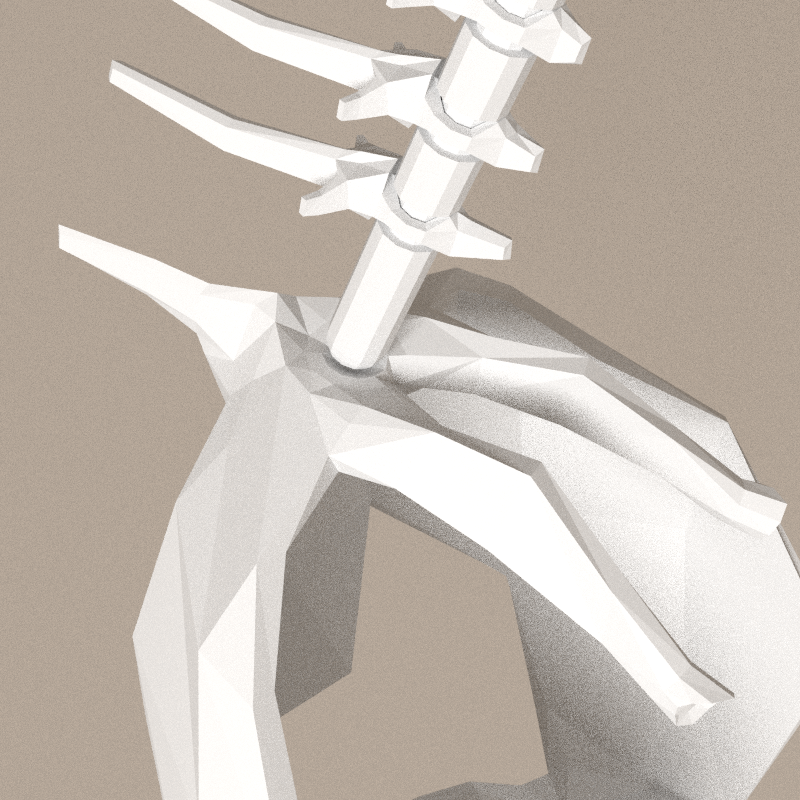
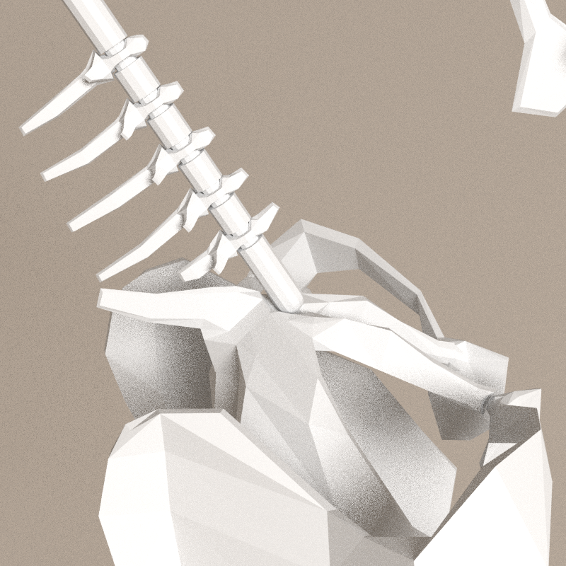
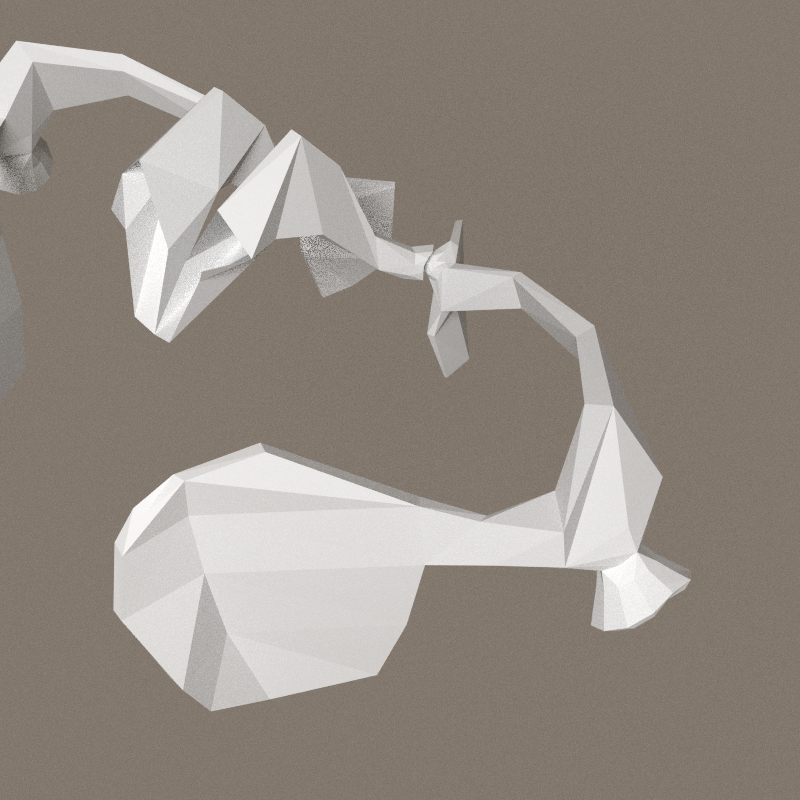
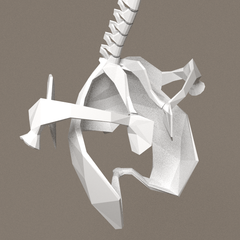
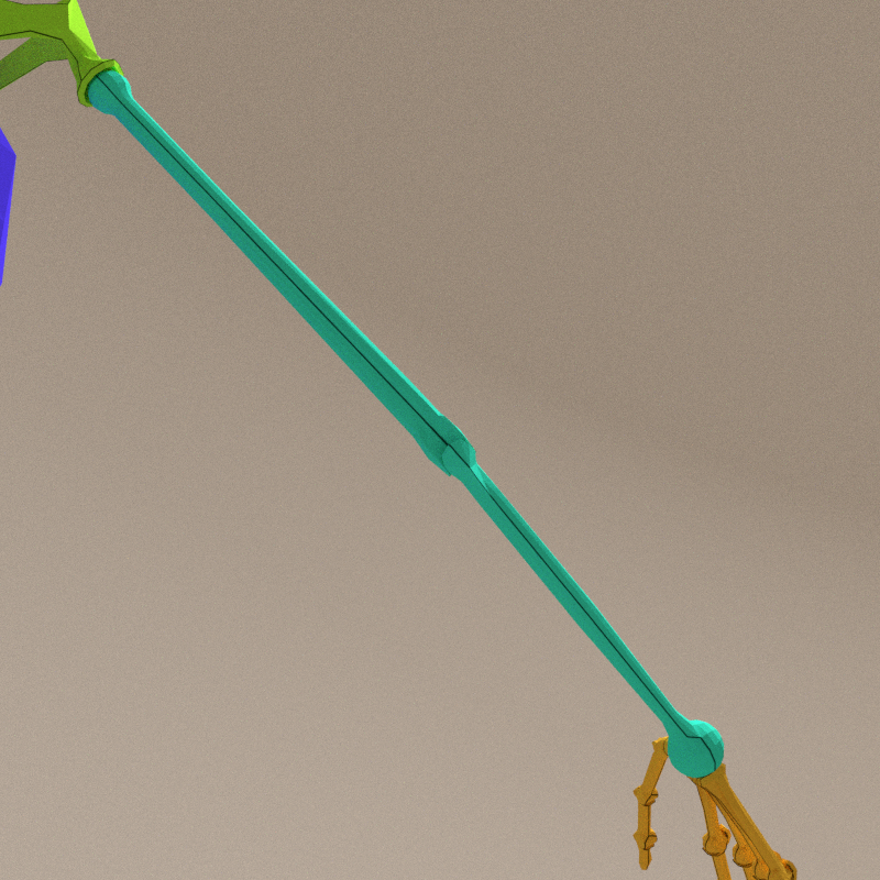
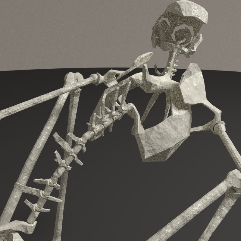
Scapula & collarbone
Finishing the shoulder girdle, with connection to humerus. The small bone going to the neck base is part of the thorax, but they have been designed here. Must be merged into the cage.


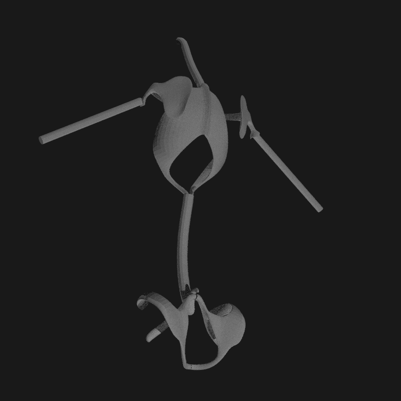
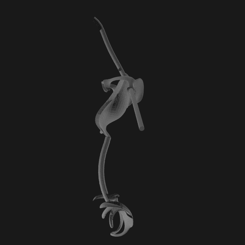
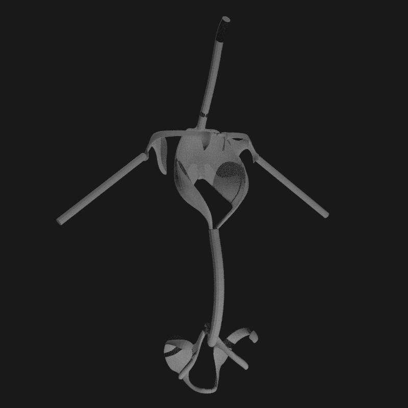
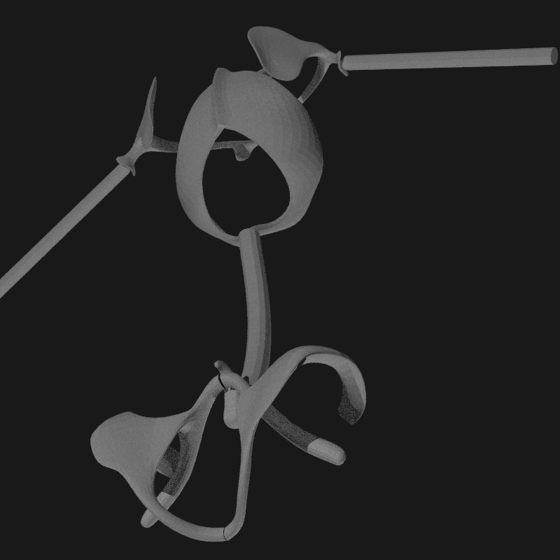
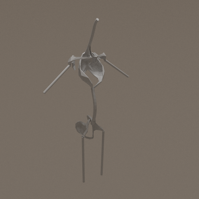
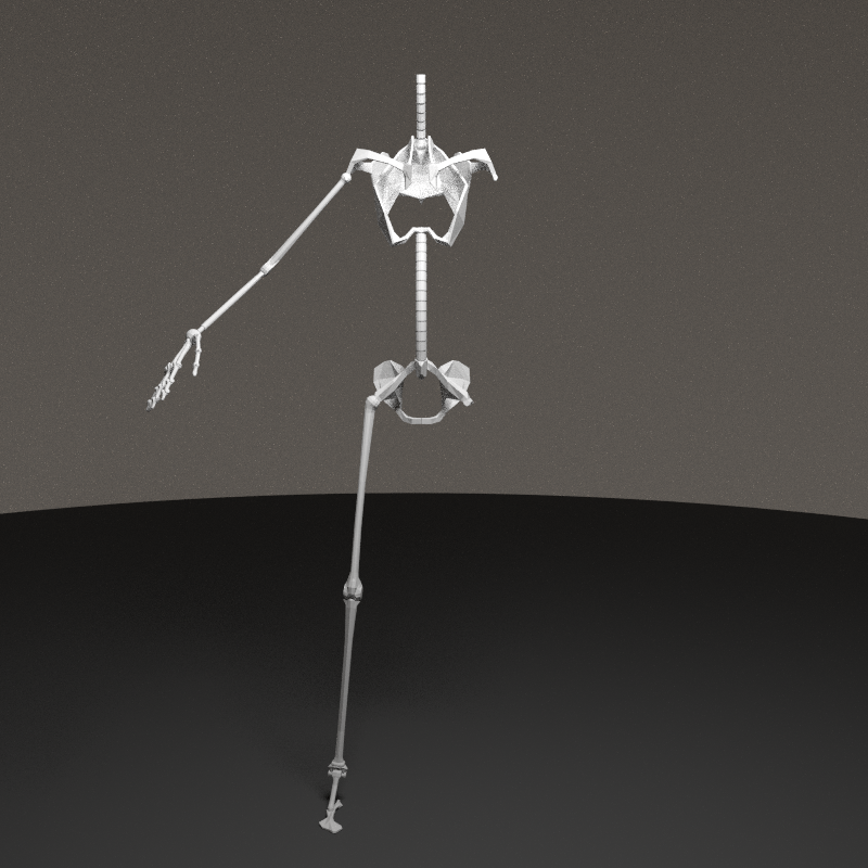
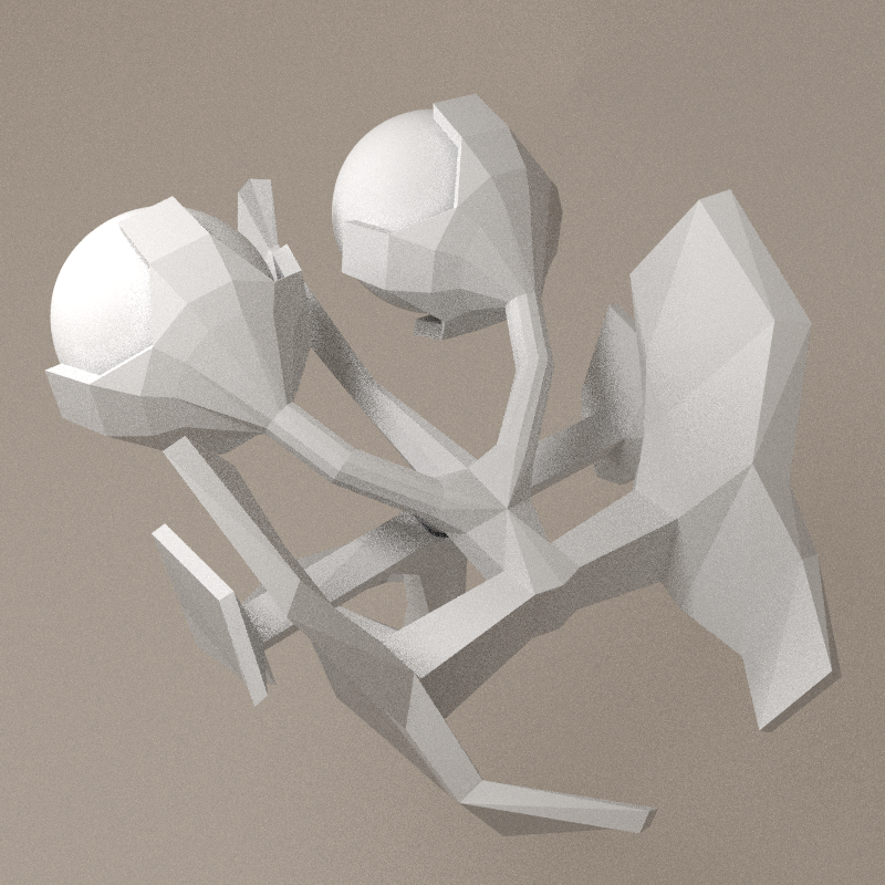
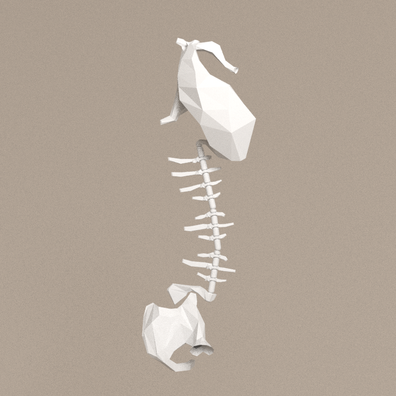
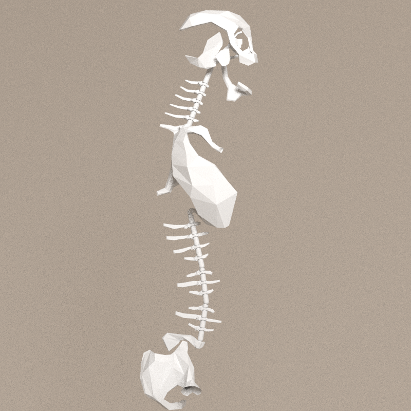
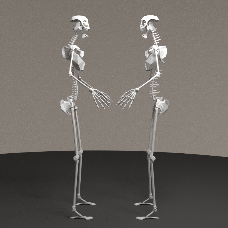
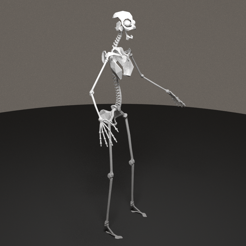
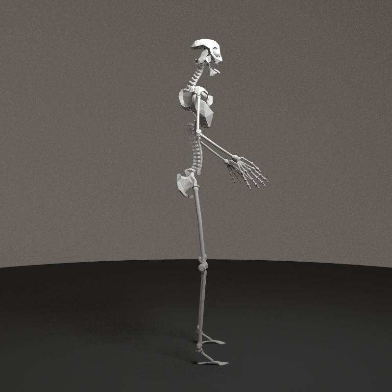
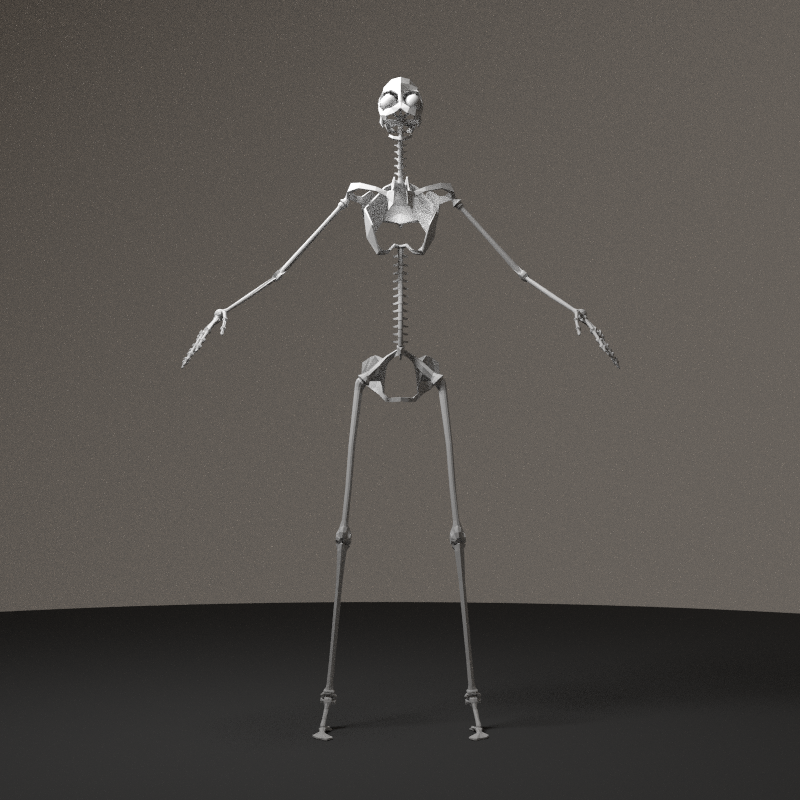
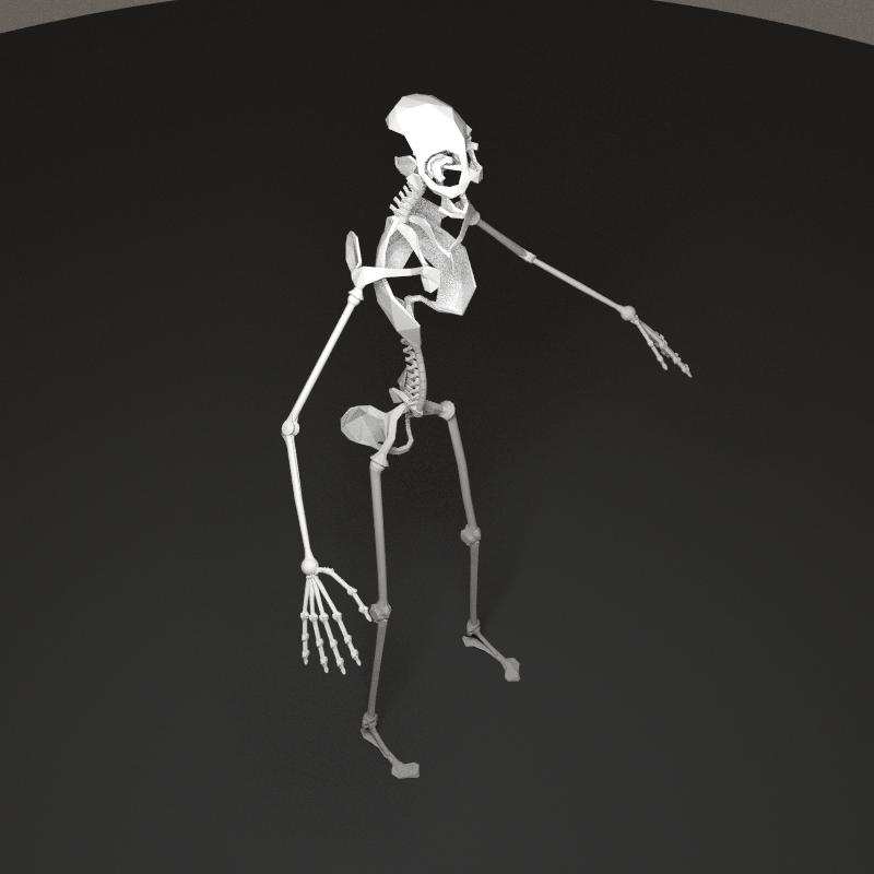
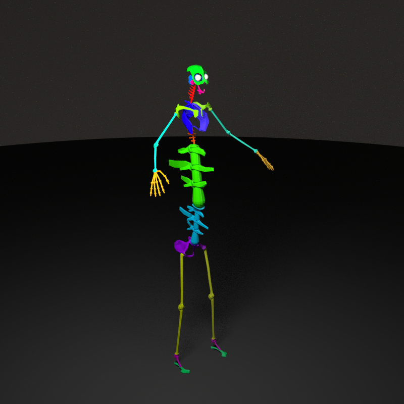
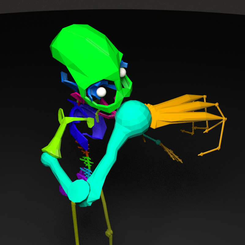
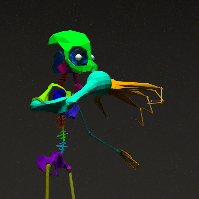
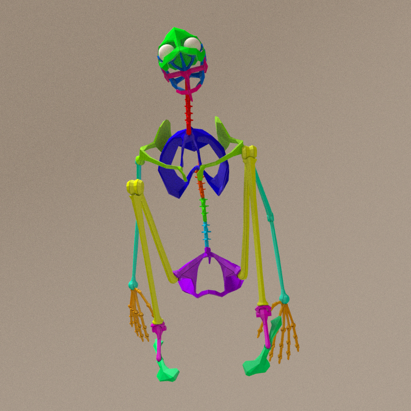
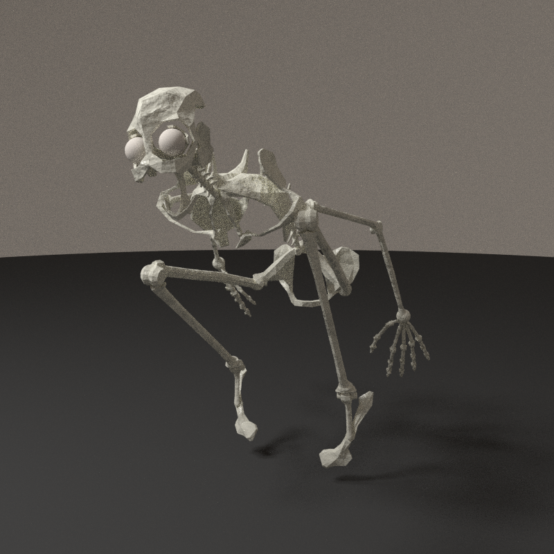
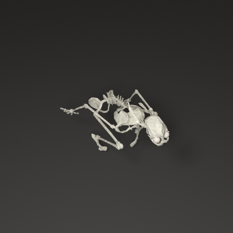
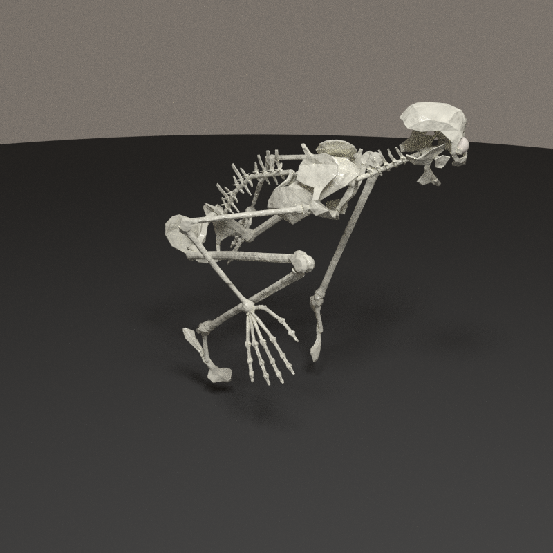
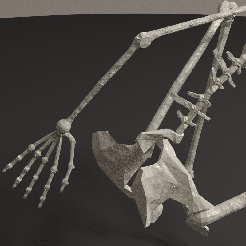
Full skeleton
First rendering of the full skeleton. The face is odd in front, and feet are too small.


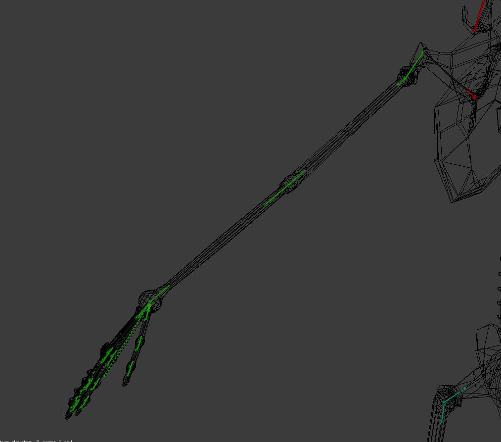
New armature
To mount the bones on a standard armature, i used makehuman. Without changing anything to the base model (a strange hermaphrodit), i went for a human IK rig.

The big advantage with the makehuman rig is that the axis are corrrectly aligned with bones. For instance, the axis of the forearm and arm are co-planar. This will help the mechanical construction a lot!
Right way to process this orientation copy in blender : Copy transforms from one object to another in blender.stackexchange.com.

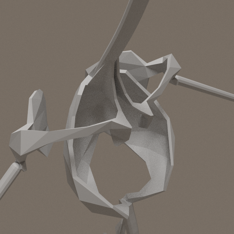
Tedious job of mixing the new armature and bones. Spine is no longer a tube.


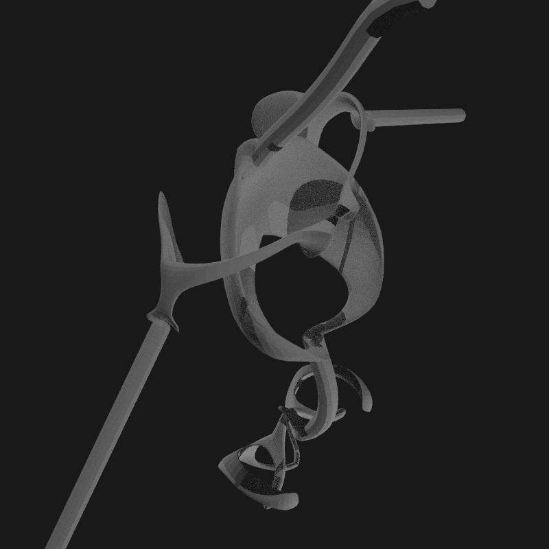
Details of articulation of the omoplate.


-
Articulations

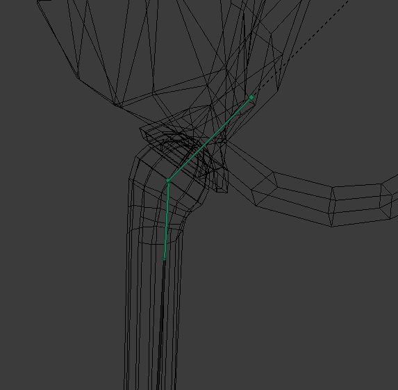
Just because i love blender UI...
Via a BoneMatrixCopy, a custom python script, i'm able to align an object precisely with a bone. Once placed, head and tail of the mesh are separated and placed at the right location: massive use of SHIT+S to place the 3D cursor, change meshes origin and move them. With a bit of method, the rotation axis of the meshes are aligned with the armature. No manual editing! > everything must be done via copy.
Process
- mesh-bone:: edit > pick vertices around the rotation points > SHIFT + S : cursor to slected
- mesh-bone:: object > transform > origin to 3d cursor
- mesh-bone:: object > SHIFT + A : apply scale and rotation
- python:: adapt bone's name and run
- the mesh-bone might not be correctly oriented - CTRL + Z, add a rotation, apply and run the script
The mesh-bone is now correctly oriented. The tail of the mesh-bone is not at the right location.
- mesh-bone:: object > SHIFT + D > ENTER ( duplication at the same place )
- mesh-bone:: edit > remove lower part of the mesh
- mesh-bone-copy:: edit > remove upper part of the mesh
- mesh-bone-copy:: edit > pick vertices around the rotation points > SHIFT + S : cursor to slected
- mesh-bone-copy:: object > transform > origin to 3d cursor
Center of the object is now aligned with rotation axis.
- armature:: edit > pick the bone's tail > SHIFT + S : cursor to slected
- mesh-bone-copy:: object > SHIFT + S : selection to cursor
- mesh-bone-copy:: object (select)
- mesh-bone:: object (SHIFT + select)
- CTRL + J : fusion of the 2 part of the mesh-bone
- mesh-bone:: edit > add the missing faces to make the mesh solid again.
Faster way to relink the 2 parts of the mesh-bone
let's assume you have 2 borders to connect (border1 & border2)
- edit the mesh
- pick a vertice on border1
- SHIFT + ALT + pick another vertice on border1 > selection of the first edge ring
- SHIFT + pick a vertice on the border2
- SHIFT + ALT + pick another vertice on border2 > selection of the second edge ring
- SPACE bar in the 3d view
- enter 'bridge in the search field
- BRDIGE EDGE LOOPS
It's not straight-forward, but it works very well.
UV unwrap
It's going to be a huge work: large bones are not flat surfaces (thorax, skull and hips for instance). Let's start the headhache.

When seams are correctly set on the mesh, blender makes a tremendous job: pixel density is very good!
On the metatarse 1 ( ankle to foot ), the seams have been difficult to place. Same at the tail of the femur.


Optimisation

After redoing the spine and therfore the uv unwrap of the vertebras and spines, an optimisation of the uvs on the texture allowed to increase a bit the size of main elements ( thorax, scapulas, hips ) and to use only one half of the texture. This was crucial to make a uv map that have 2 sides ( left and right ).

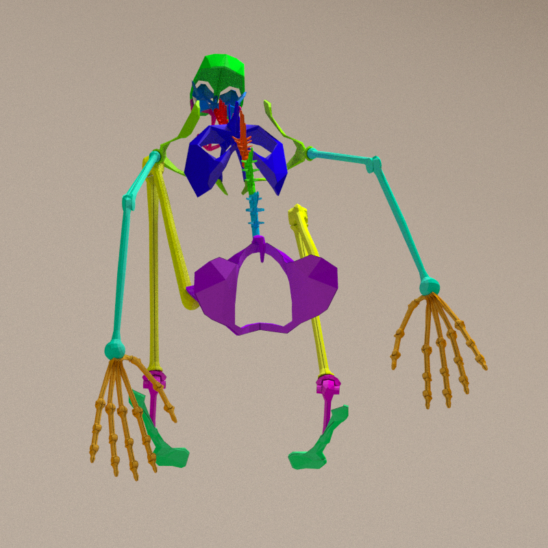
Different colors for each bone area. Results are pretty cool when the texture is used. Glitches on the knee and the ankle comes from texture.
There was a pixel density[4] problem on the top process of the thorax. It has been separated from the main shape and the result is ok.


Rigging
Based on makehuman export, the armature required adaptaton to allow the flexibility i need.
Scaling issue
The tanuki can be deformed in all possible ways. The scaling is a big problem with the current armature. The articulations can not be deformed when scaling is not homogeneous. And even if it is, the 2 parts of the articulation must receive the same scaling, even if they are NOT on the same armature's bone.

With only one armature's bone for the humerus, it's impossible to achieve: a Y scaling on the abone[5] will deform both ends of the mbone[6] and make the articulation not functional: the pivot becomes an elliptic shape.

Each stretchable bone must have 3 parts: head, body ands tail.
If the scaling is homogeneous, it is applied on:
- tail of the parent bone
- head, body and tail of current bone
- head of the child node(s)
To stretch the bone, the scale on Y axis in this case is only applied on the body of current bone.
Result


Each long abone[5] is splitted in 3 part:
- *_head
- *_body
- *_tail
On hip articulation, a small abone[5] has been added to allow the scaling of the head of the femur. If not, the head of the femur would grow larger than the cavity holding it.

After skinning, the bones have a perfect behaviour on scale. Both half-avatar have the same bones'orientations.
Ankle

Rotations on this articulation must be divided in two parts:
- X & Z are applied on the tarse
- Y is applied on metatarse_1_head
The tibia_tail is there only to avoid deformation of the contact surface with the tarse.
Skinning
I had a bad feeling about this on the spine. The idea was to have a common weight in each vertebra, but the result is ABSOLUTLY not good!

And here is how the weighting has been done:

( vertebras are numbered from bottom )
- vertebra 1: hips - 75% | lumber 1 - 25%
- vertebra 2: hips - 50% | lumber 1 - 50%
- vertebra 3: hips - 25% | lumber 1 - 75%
- vertebra 4: hips - 0% | lumber 1 - 100%
Attempt to solve the issue: same weight at the intersections + spinous and transverse processes[3].

After an attempt to fix this via weights, i have to admit the brutal truth: there's no way this will ever works. The bones of the spine MUST follows the same logic as all the others: 1 mbone[6] per abone[5].
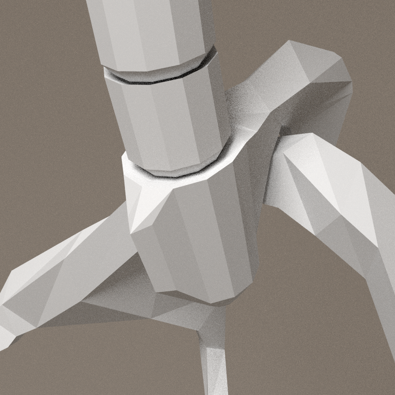
Spine mechanic
After a remodelling of the spine, rigging can continue. Even if placed here, the reflexion about rigging was guiding the modelling...
Solving the rotation repartition along the vertebras:

It seems that the top vertebra of each spine's bone should be joint to the spine ( small schema in green and red at the bottom right of the sketch ). If not, nothing is pulling on the spine... It could be reverse: muscles are pulling on the vertebras, the spine being influenced by the forces applied position itself at the best location to reduce effort. To keep the spine upright, muscles should then pull in all direction with the same force. The connections between spines can be fixed and hold together by simple tendons between ends.
Spine's bones are passive > nothing is pulling them directly. The whole spine becomes a dynamic structure, completly loose without the muscles. The direction and shapes of back and thoracic musculature becomes crucial. I like the idea.
Result bone structure:
- 3 spine_lumber_* and 1 spine_cervical abones[5]
- each vertebra has its own abone, parented to the spine
- vertebras have 2 parts ( _head & _body ) to allow deformations
- vertebras are numbered from the bottom, 1 > 15


Maths of the vertebras:
- lumbers doesn't rotate in Y axis ( direction of the bones )
- it pass the rotation to the next spine's lumber
- it apply a percentage of the rotation on the vertebras, rule: distance to origin == percentage. If the lumber has 3 vertebras, first is 33%, next 66% and last 100%
This means that the rotation to apply must be splitted in 2 parts:
- X and Z are applied on the lumber, directly
- Y on its childs, depending on the distance
Armature - vertex groups sync
The armature have been adapted for spine mechanic. This means the vertex groups of the mesh are no longer in sync with the armature > new vertex groups must be created. To avoid losing the work already done, a python script must be created. It will verify that all abones[5]'s name exists in vertex groups. If not the vertex group will be created. If a bone doesn't exists anymore, the vertex group will be deleted.
Script was simple to write: BonesVertexgroupsSync. The new bones are now available in the vertex group panel.
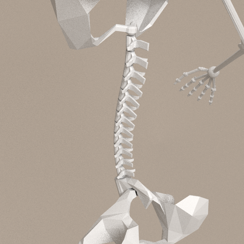
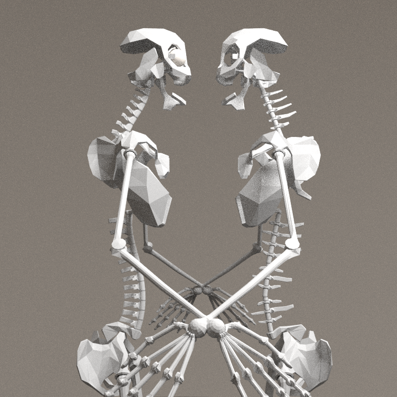
Center and right side of the skeleton - 08/04/2016

Batch pose bone modification
Due to the number of bones of my armature and the regular modification of its structure, adjusting bones params manually has slowly become impossible. Python helps once again. See BatchBonesModification.py
The blender UI evolves gradually to follow the incerasing complexity of the work. The properties and outliner panels are now taking the whole height of the screen, a big script panel is open to develop and the right part of the left screen is filled with the transform panel of the 3d view, constantly open to verify positions.

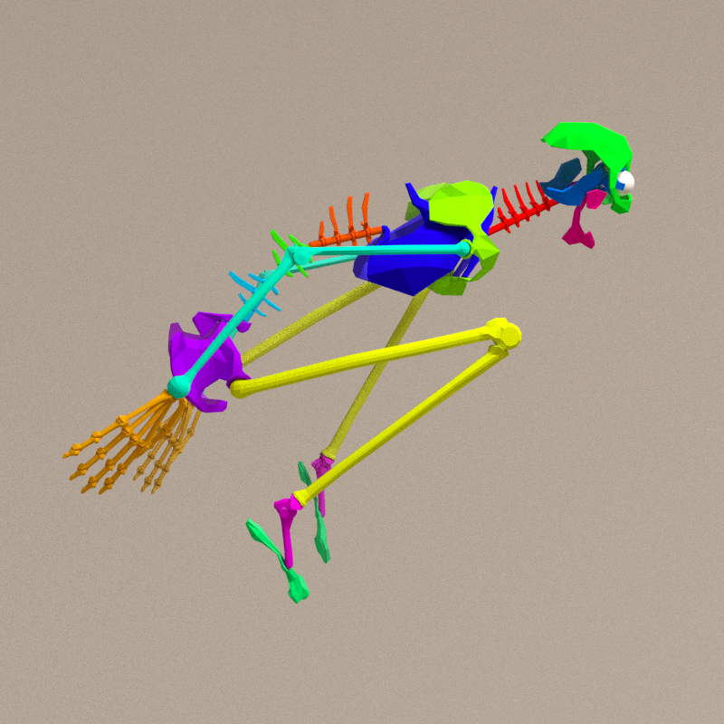
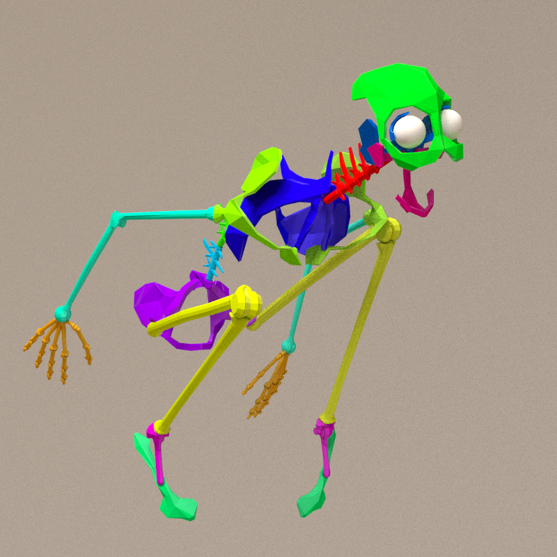
Testing the rotations limits and scale inheritances with extremes poses, it remains mechanically correct.


Mirroring
Due to the precision i want to achieve in the skinning, it will take ages to do it 2 times, for left and right part of the skeleton. Relations between armature and mesh is based on vertex groups'names (hopefully). Therefore, i can skin only the right side of the skeleton and mirror it once done. And save a lot of time.
The first thing to do is to glu the 2 sides of the skeleton together. This has to be done this way to edit the UV map before the fusion. Undoable via a modifier. Therefore, i wrote a script to do it: GlueVertices. It's a recursive script, so it will take some time to process...
The renaming can be done via a small piece of script: BonesAndVertexgroupsBulkRenaming
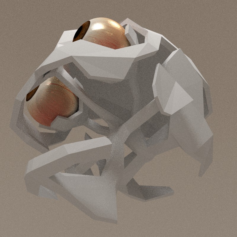
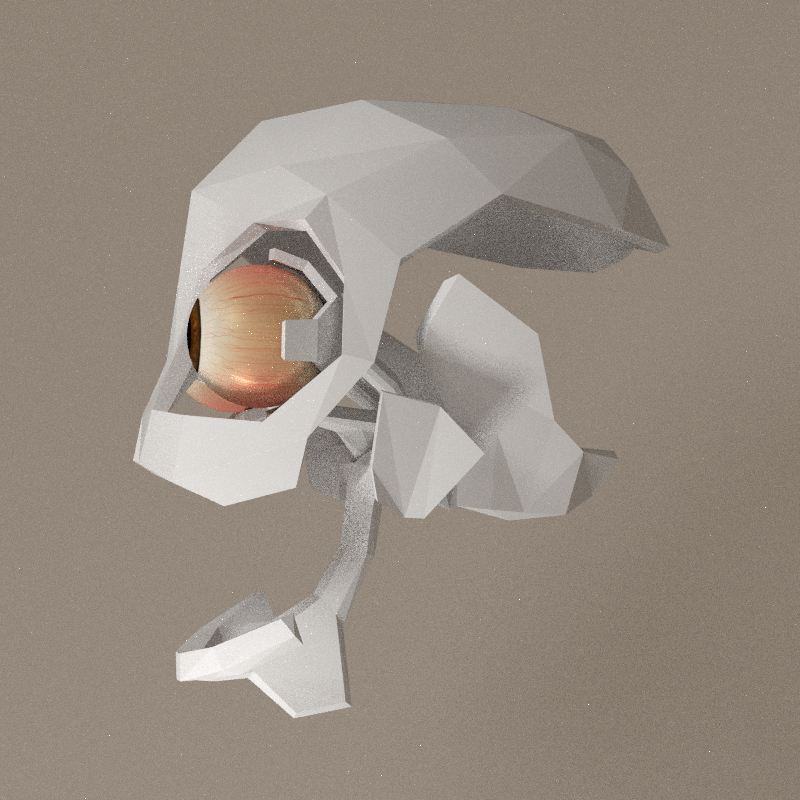
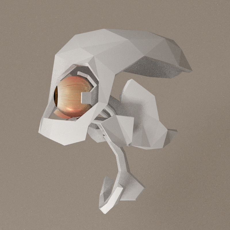
Fine-tuning

Several adaptations had to be made in head and pelvis:
- abones[5] "orbit": avoid the claw that holds the eye ball to lose contact with the ball
- cervical-skull connection: head abone had to been subdivided
- skull-jaw: addition of a tail bone between the head and jaw abone to control articulation size
- hips-lumber: same process
Numbers
- 17 rotation bones per arm (including hand)
- 5 rotation bones per leg (including foot)
- 17 rotation bones for spine & head
- 61 rotation bones
- 147 control and scale bones
Grand total: 208 bones in the armature
Control and scale abones are nearly 3 times more present due to scaling issue and spine mechanic.
Mesh and armature are now in good sync. Modification of the length of any bone has no effect on the articulation consistency.
- It's possible to inflate the complete structure by scaling up _body and _tail abones together;
- _head abones inherits scale from their tail, making the scaling of the articulation possible - see screenshots.
Unreal 4 import

Fist import in unreal. Result is good if:
- fbx contains only armature and mesh
- normals are correct in blender (...)
- option Import normals and tangents' is checked
Strange things:
- rotation speed is abnormally small: an visual 5° degree rotation demands a 360° rotation in editor...
Resource to check:
- Unreal Engine 4, Import a Skeletal Mesh with Animations and Cloth Physics from Blender - Part 1 on youtube
Texture


First attempt, based on http://blendermada.com/materials/detail/26-cracked-stone/
On the model
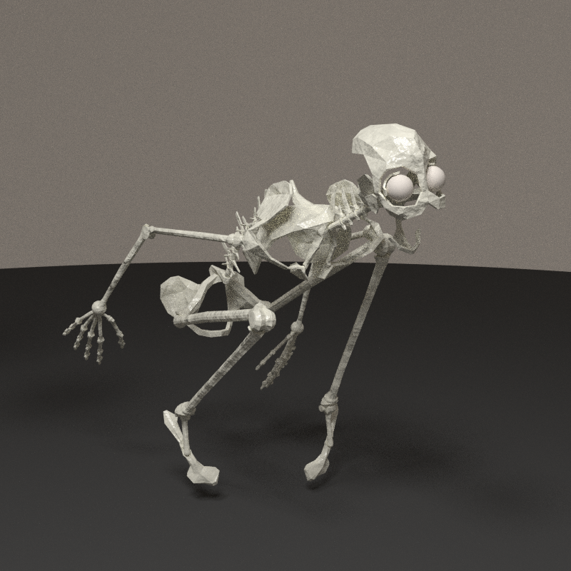
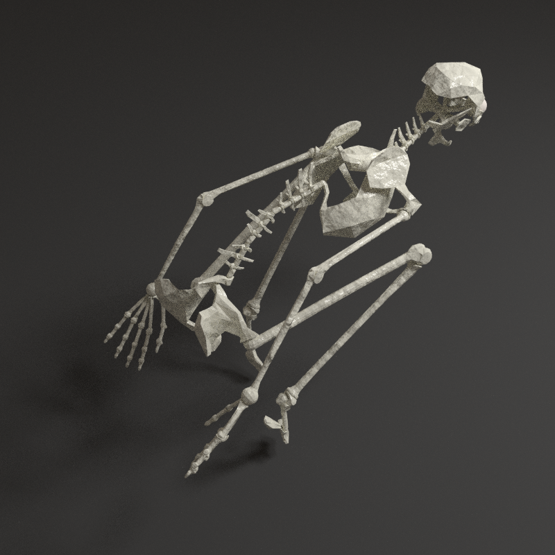

Work is nearly finished here, the texture will be part of another reflexion, global to the model. It's time to move to the muscles!
Foot notes
- ↑ Hugh Herr is a researcher at the MIT, working on artificial legs. profile on MIT lab - bionxmed, the company selling the prosthetic
- ↑ 2.0 2.1 2.2 2.3 2.4 Terms of motion in anatomy, definition in wikipedia
- ↑ 3.0 3.1 vetebra's process: see Vertebra_Superior_View in wikipedia
- ↑ Pixel density: the concept is usually related to displays, describing the number of pixels per cm2 - wikipedia. I use it to express the number of pixels per faces' surface. The result here is a compromise between constant density and avoiding too small objects
- ↑ 5.0 5.1 5.2 5.3 5.4 5.5 5.6 abone: shortcut for armature's bone (the logical part of the skeleton), by opposition to the mesh bone (the visible part of the skeleton)
- ↑ 6.0 6.1 mbone: shortcut for mesh bone (the visible part of the skeleton), by opposition to the armature's bone (the logical part of the skeleton)
Resources
Backup
- File:Skeleton-model-backup.zip - .blend file + refs folder
Externals
- BIODIGITAL HUMAN - website to explore 3d anatomy.
- Base de l'anatomie humaine - projet de Edouard Ceysson et Loup Dédiot.
Theory
- UV unwrapping with force-directed graph drawing
- UV unwrapping with squares conformal maps - File:Least Squares Conformal Maps.pdf
Books